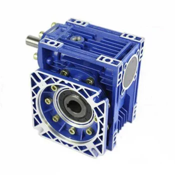
Product Description
Xhw85pg4 Part Electric or Manual Operator Turn Quadrant Wormgear Two-Stage Worm Gearbox for Valve |
|||||||||||||||||||||||||||||||||||||||||||||||||||||||||||||||||||||||||||||||||||||||||||||||||||||||||||||||||||||||||||||||||||||||||||||||||||||||||||||||||||||||||||||||||||||||||||||||||||||||||||||||||||||||||||||||||||||||||||||||||||||||||||||||||||||||||||||||||||||||||||||||||||||||||||||||||||||||||||||||||||||||||||||||||||||||||||||||||||||||||||||||||||||||||||||||||||||||||||||||||||||||||||||||||||||||||||||||||||||||||
|
|
|||||||||||||||||||||||||||||||||||||||||||||||||||||||||||||||||||||||||||||||||||||||||||||||||||||||||||||||||||||||||||||||||||||||||||||||||||||||||||||||||||||||||||||||||||||||||||||||||||||||||||||||||||||||||||||||||||||||||||||||||||||||||||||||||||||||||||||||||||||||||||||||||||||||||||||||||||||||||||||||||||||||||||||||||||||||||||||||||||||||||||||||||||||||||||||||||||||||||||||||||||||||||||||||||||||||||||||||||||||||||
| NO. | Description | Material | Material number |
| 1 | Bolts | Carbon Steel | ASTM A29M-1571 |
| 2 | Indicator Plate | Carbon Steel | ASTM A29M-1571 |
| 3 | O-ring | Rubber | NBR |
| 4 | Oil seal | Rubber | NBR |
| 5 | Handwheel indicator | Carbon Steel | ASTM A29M-1571 |
| 6 | Bolts | Carbon Steel | ASTM A29M-1045 |
| 7 | Cover | Carbon Steel/ Ductile iron | ASTM A216 WCB/ ASTM A536 65-45-12 |
| 8 | Sealing Gasket | Insulation paper | |
| 9 | Worm Gear | Ductile iron | ASTM A536 65-45-12 |
| 10 | Stem Bush | Carbon Steel | ASTM A29M-1571 |
| 11 | Snap Ring | Carbon Steel | ASTM A29-1566 |
| 12 | End Cover | Carbon Steel | ASTM A29M-1571 |
| 13 | Bearing | Alloy Steel | ASTM A295-52100 |
| 14 | Body | Carbon Steel/ Ductile iron | ASTM A216 WCB/ ASTM A536 65-45-12 |
| 15 | Grease Nipple | Carbon Steel | ASTM A29M-1571 |
| 16 | Worm | Carbon Steel | ASTM A29M-1045 |
| 17 | Key | Carbon Steel | ASTM A29M-1045 |
| 18 | Reduction body | Carbon Steel/ Ductile iron | ASTM A216 WCB/ ASTM A536 65-45-12 |
| 19 | Bolts | Carbon Steel | ASTM A29M-1045 |
| 20 | Bearing | Alloy Steel | ASTM A295-52100 |
| 21 | Gears | Carbon Steel | ASTM A29M-1045 |
| 22 | Snap Ring | Carbon Steel | ASTM A29-1566 |
| 23 | Reduction cover | Carbon Steel/ Ductile iron | ASTM A216 WCB/ ASTM A536 65-45-12 |
| 24 | Washer of nuts | Carbon Steel | ASTM A29M-1571 |
| 25 | Adjusting nuts | Carbon Steel | ASTM A29M-1045 |
| 26 | Adjusting Bolts | Carbon Steel | ASTM A29M-1045 |
Dimension
| DIM MODEL |
Mounting Base | External Part | Input Shaft Part | Handwheel | |||||||||||||||
| Type | Flange Size | D1 | P.C.D | D3 | H0 | H1 | H2 | K | K1 | K2 | K3 | L | L2 | L1 | PD | KEY | M | ||
| D2 | N-H-DP | ||||||||||||||||||
| KB-0-1S | A |
F-12 | 85 | 125 | 4-M12-18 | 150 | 3 | 66 | 204 | 91 | 48 | 51 | 220 | 83 | 161 | 31 | 21 | 6 | 300 |
| KB-01-1S | F-14 | 100 | 140 | 4-M16-24 | 175 | 4 | 75 | 225 | 94 | 48 | 61 | 276 | 93 | 171 | 31 | 21 | 6 | 350 | |
| KB-02-1S | F-16 | 130 | 165 | 4-M20-30 | 210 | 5 | 92 | 286 | 110 | 64 | 68 | 350 | 113 | 205 | 40 | 28 | 8 | 450 | |
| KB-03-1S | B |
(F-20) | 140 | 205 | 8-M16-24 | 250 | 5 | 111 | 325 | 112 | 58 | 68 | 362 | 126 | 217 | 40 | 28 | 8 | 500 |
| KB-04-1S | F-25 | 200 | 254 | 8-M16-24 | 300 | 5 | 144 | 383 | 124 | 63 | 100 | 426 | 158 | 246 | 40 | 28 | 8 | 600 | |
| KB-05-1S | F-30 | 230 | 298 | 8-M20-30 | 350 | 5 | 160 | 453 | 143 | 71 | 101 | 464 | 190 | 284 | 40 | 28 | 8 | 650 | |
| KB-06-1S | F-35 | 260 | 356 | 8-M30-45 | 415 | 5 | 200 | 525 | 169 | 91 | 119 | 498 | 224 | 318 | 40 | 28 | 8 | 700 | |
| KB-07-1S | B | F-40 | 300 | 406 | 8-M36-54 | 475 | 8 | 225 | 619 | 190 | 101 | 155 | 457 | 237 | 417 | 60 | 38 | 10 | 800 |
| KB-08-1S | F-40 | 300 | 406 | 8-M36-50 | 475 | 8 | 270 | 668 | 201 | 102 | 155 | 499 | 279 | 459 | 60 | 38 | 10 | 900 | |
| KB-09-1S | C | F-48 | 370 | 483 | 12-M36-54 | 560 | 8 | 338 | 790 | 232 | 116 | – | 561 | 341 | 521 | 60 | 38 | 10 | 900 |
Technical Parameters
| PARA MODEL |
Ratio |
Flange Size (ISO5211) | Max Valve Stem dmax | Max Torque | M.A. | Weight | |
| Input | Output | ||||||
| mm | Nm | Nm | 10% | Kg | |||
| KB-0-1S | 63:1 | F-12 | 40 (12 X 8) | 65 | 1000 | 16.1 | 19 |
| KB-01-1S | 74:1 | F-14 | 50 (14 X 9) | 100 | 1850 | 18.9 | 21 |
| KB-02-1S | 129:1 | F-16 | 60 (18 X 11) | 90 | 3000 | 33 | 38 |
| KB-03-1S | 158:1 | ( F-20 ) | 70 (20 X 12) | 105 | 4200 | 40 | 41 |
| KB-04-1S | 179:1 | F-25 | 90 (25 X 14) | 160 | 6500 | 41 | 64 |
| KB-05-1S | 177:1 | F-30 | 105 (28 X 16) | 225 | 10000 | 45 | 91 |
| KB-06-1S | 201:1 | F-35 | 120 (32 X 18) | 295 | 15000 | 51 | 137 |
| KB-07-1S | 202:1 | F-40 | 140 (36 X 20) | 590 | 28000 | 48 | 220 |
| KB-08-1S | 244:1 | F-40 | 165 (40 X 22) | 890 | 48000 | 54 | 290 |
| KB-09-1S | 234:1 | F-48 | 190 (45 X 25) | 1300 | 72000 | 56 | 450 |
Remark:
input torque=output torque/M.A.
Related products
We provides a reliable grantee for the product’ s quality by advanced inspection and testing equipment. professional technical team, exquisite processing technology and strict control system.
In recent years, the company has been developing rapidly by its rich experience in production, advanced management system, standardized management system, strong technical force. We always adhere the concept of survival by quality, and development by innovation in science and technology.
Our Group is willing to work with you hand in hand and create brilliance together!
Material available
Low carbon steel, C45, 20CrMnTi, 42CrMo, 40Cr, stainless steel. Can be adapted regarding customer requirements.
Surface treatment
Blacking, galvanization, chroming, electrophoresis, color painting, …
Heat treatment
High frequency quenching heat treatment, hardened teeth, carbonizing, nitride, …
FAQ:
Q: Are you trading company or manufacturer ?
A: Our group consists in 3 factories and 2 abroad sales corporations.
Q: Do you provide samples ? is it free or extra ?
A: Yes, we could offer the sample for free charge but do not pay the cost of freight.
Q: How long is your delivery time ? What is your terms of payment ?
A: Generally it is 40-45 days. The time may vary depending on the product and the level of customization. For standard products, the payment is: 30% T/T in advance ,balance before shippment.
Q: What is the exact MOQ or price for your product ?
A: As an OEM company, we can provide and adapt our products to a wide range of needs.Thus, MOQ and price may greatly vary with size, material and further specifications; For instance, costly products or standard products will usually have a lower MOQ. Please contact us with all relevant details to get the most accurate quotation.
If you have another question, please feel free to contact us.
/* January 22, 2571 19:08:37 */!function(){function s(e,r){var a,o={};try{e&&e.split(“,”).forEach(function(e,t){e&&(a=e.match(/(.*?):(.*)$/))&&1
| Application: | Machinery, Marine, Toy, Agricultural Machinery |
|---|---|
| Function: | Change Drive Torque, Speed Changing, Speed Reduction |
| Layout: | Wrom |
| Hardness: | Hardened Tooth Surface |
| Installation: | Worm Reducer |
| Step: | Worm Drive |

How to Install and Align a Worm Reducer Properly
Proper installation and alignment of a worm reducer are crucial for ensuring optimal performance and longevity. Follow these steps to install and align a worm reducer:
- Preparation: Gather all the necessary tools, equipment, and safety gear before starting the installation process.
- Positioning: Place the worm reducer in the desired location, ensuring that it is securely mounted to a stable surface. Use appropriate fasteners and mounting brackets as needed.
- Shaft Alignment: Check the alignment of the input and output shafts. Use precision measurement tools to ensure that the shafts are parallel and in line with each other.
- Base Plate Alignment: Align the base plate of the reducer with the foundation or mounting surface. Ensure that the base plate is level and properly aligned before securing it in place.
- Bolt Tightening: Gradually and evenly tighten the mounting bolts to the manufacturer’s specifications. This helps ensure proper contact between the reducer and the mounting surface.
- Check for Clearance: Verify that there is enough clearance for any rotating components or parts that may move during operation. Avoid any interference that could cause damage or performance issues.
- Lubrication: Apply the recommended lubricant to the worm reducer according to the manufacturer’s guidelines. Proper lubrication is essential for smooth operation and reducing friction.
- Alignment Testing: After installation, run the worm reducer briefly without a load to check for any unusual noises, vibrations, or misalignment issues.
- Load Testing: Gradually introduce the intended load to the worm reducer and monitor its performance. Ensure that the reducer operates smoothly and efficiently under the load conditions.
It’s important to refer to the manufacturer’s installation guidelines and specifications for your specific worm reducer model. Proper installation and alignment will contribute to the gearbox’s reliability, efficiency, and overall functionality.

Does a Worm Reducer Require Frequent Maintenance?
Worm reducers generally require less frequent maintenance compared to some other types of gearboxes due to their design and operating characteristics. However, maintenance is still essential to ensure optimal performance and longevity. Here are some key points to consider:
- Lubrication: Proper lubrication is crucial for worm gearboxes. Regularly check the lubricant level and quality to prevent wear and overheating. Lubricant should be changed as recommended by the manufacturer.
- Inspections: Periodically inspect the gearbox for signs of wear, damage, or oil leaks. Check for any unusual noises, vibrations, or changes in performance that could indicate a problem.
- Tightening and Alignment: Check and tighten any loose fasteners and ensure that the gearbox is properly aligned. Misalignment can lead to increased wear and reduced efficiency.
- Seal Maintenance: Inspect and maintain seals to prevent oil leakage and contaminants from entering the gearbox.
- Cleaning: Keep the gearbox clean from debris and contaminants that could affect its performance. Regular cleaning can prevent premature wear and damage.
- Load and Speed: Ensure that the gearbox is operating within its rated load and speed limits. Exceeding these limits can lead to accelerated wear and potential failure.
- Environmental Conditions: Consider the operating environment of the gearbox. Extreme temperatures, humidity, and other factors can impact the gearbox’s performance and longevity.
While worm gearboxes are known for their durability and self-locking feature, neglecting maintenance can lead to premature wear, reduced efficiency, and potential breakdowns. Following the manufacturer’s recommendations for maintenance intervals and procedures is essential to keep the worm reducer in optimal condition.

Advantages of Using a Worm Reducer in Mechanical Systems
Worm reducers offer several advantages that make them suitable for various mechanical systems:
- High Gear Reduction Ratio: Worm gearboxes provide significant speed reduction, making them ideal for applications that require a high gear reduction ratio without the need for multiple gears.
- Compact Design: Worm reducers have a compact and space-saving design, allowing them to be used in applications with limited space.
- Self-Locking: Worm gearboxes exhibit self-locking properties, which means that the worm screw can prevent the worm wheel from reversing its motion. This is beneficial for applications where the gearbox needs to hold a load in place without external braking mechanisms.
- Smooth and Quiet Operation: Worm gearboxes operate with a sliding motion between the teeth, resulting in smoother and quieter operation compared to some other types of gearboxes.
- High Torque Transmission: Worm gearboxes can transmit high torque levels, making them suitable for applications that require powerful torque output.
- Heat Dissipation: The sliding action between the worm screw and the worm wheel contributes to heat dissipation, which can be advantageous in applications that generate heat during operation.
- Stable Performance: Worm reducers offer stable and reliable performance, making them suitable for continuous operation in various industrial and mechanical systems.
Despite these advantages, it’s important to note that worm gearboxes also have limitations, such as lower efficiency compared to other gear types due to the sliding motion and potential for higher heat generation. Therefore, selecting the appropriate type of gearbox depends on the specific requirements and constraints of the application.


editor by CX 2024-04-10
China Hot selling Manual Gearbox with Hand Wheel for Valve Control with Best Sales
Product Description
Focusing on the mindset to provide better products and services to customers, to improve customer work efficiency and ensure the safe use of product, STHANS devotes to develop and update products continuously.
We are striving to provide you excellent technology, more innovative products and higher quality standards for the actuator mechanism, handwheel and other pneumatic accessories.
Our newly developed handwheel mechanism is widely used in various valves. It has also become 1 of the indispensable component for installation debugging and air supply failure under severe working conditions.
/* January 22, 2571 19:08:37 */!function(){function s(e,r){var a,o={};try{e&&e.split(“,”).forEach(function(e,t){e&&(a=e.match(/(.*?):(.*)$/))&&1
| Application: | Valve Industry |
|---|---|
| Function: | Distribution Power |
| Layout: | Three-Ring |
| Hardness: | Soft Tooth Surface |
| Installation: | Torque Arm Type |
| Step: | Stepless |
| Samples: |
US$ 111/Piece
1 Piece(Min.Order) | |
|---|
| Customization: |
Available
| Customized Request |
|---|
Common Problems and Troubleshooting for Worm Gearboxes
Worm gearboxes, like any mechanical component, can experience various issues over time. Here are some common problems that may arise and possible troubleshooting steps:
- Overheating: Overheating can occur due to factors such as inadequate lubrication, excessive loads, or high operating temperatures. Check lubrication levels, ensure proper ventilation, and reduce loads if necessary.
- Noise and Vibration: Excessive noise and vibration may result from misalignment, worn gears, or improper meshing. Check for misalignment, inspect gear teeth for wear, and ensure proper gear meshing.
- Leakage: Oil leakage can be caused by damaged seals or gaskets. Inspect seals and gaskets, and replace them if necessary.
- Reduced Efficiency: Efficiency loss can occur due to friction, wear, or misalignment. Regularly monitor gearbox performance, ensure proper lubrication, and address any wear or misalignment issues.
- Backlash: Excessive backlash can affect precision and accuracy. Adjust gear meshing and reduce backlash to improve performance.
- Seizure or Binding: Seizure or binding can result from inadequate lubrication, debris, or misalignment. Clean the gearbox, ensure proper lubrication, and address misalignment issues.
- Worn Gears: Worn gear teeth can lead to poor performance. Regularly inspect gears for signs of wear, and replace worn gears as needed.
- Seal Wear: Seals can wear over time, leading to leakage and contamination. Inspect seals regularly and replace them if necessary.
If you encounter any of these problems, it’s important to address them promptly to prevent further damage and maintain the performance of your worm gearbox. Regular maintenance, proper lubrication, and addressing issues early can help extend the lifespan and reliability of the gearbox.

Worm Gearbox vs. Helical Gearbox: A Comparison
Worm gearboxes and helical gearboxes are two popular types of gear systems, each with its own set of advantages and disadvantages. Let’s compare them:
| Aspect | Worm Gearbox | Helical Gearbox |
| Efficiency | Lower efficiency due to sliding friction between the worm and worm wheel. | Higher efficiency due to rolling contact between helical gear teeth. |
| Torque Transmission | Excellent torque transmission and high reduction ratios achievable in a single stage. | Good torque transmission, but may require multiple stages for high reduction ratios. |
| Noise and Vibration | Generally higher noise and vibration levels due to sliding action. | Lower noise and vibration levels due to smoother rolling contact. |
| Backlash | Higher inherent backlash due to the design. | Lower backlash due to meshing of helical teeth. |
| Efficiency at Higher Speeds | Less suitable for high-speed applications due to efficiency loss. | More suitable for high-speed applications due to higher efficiency. |
| Overload Protection | Natural self-locking feature provides some overload protection. | May not have the same level of inherent overload protection. |
| Applications | Commonly used for applications requiring high reduction ratios, such as conveyor systems and heavy-duty machinery. | Widely used in various applications including automotive transmissions, industrial machinery, and more. |
Both worm and helical gearboxes have their place in engineering, and the choice between them depends on the specific requirements of the application. Worm gearboxes are preferred for applications with high reduction ratios, while helical gearboxes are chosen for their higher efficiency and smoother operation.

Lubrication Requirements for a Worm Gearbox
Lubrication is crucial for maintaining the performance and longevity of a worm gearbox. Here are the key considerations for lubricating a worm gearbox:
- Type of Lubricant: Use a high-quality, high-viscosity lubricant specifically designed for worm gearboxes. Worm gearboxes require lubricants with additives that provide proper lubrication and prevent wear.
- Lubrication Interval: Follow the manufacturer’s recommendations for lubrication intervals. Regularly check the gearbox’s temperature and oil condition to determine the optimal frequency of lubrication.
- Oil Level: Maintain the proper oil level to ensure effective lubrication. Too little oil can lead to insufficient lubrication, while too much oil can cause overheating and foaming.
- Lubrication Points: Identify all the lubrication points on the gearbox, including the worm and wheel gear surfaces. Apply the lubricant evenly to ensure complete coverage.
- Temperature: Consider the operating temperature of the gearbox. Some lubricants have temperature limits, and extreme temperatures can affect lubricant viscosity and performance.
- Cleanliness: Keep the gearbox and the surrounding area clean to prevent contaminants from entering the lubricant. Use proper filtration and seals to maintain a clean environment.
- Monitoring: Regularly monitor the gearbox’s temperature, noise level, and vibration to detect any signs of inadequate lubrication or other issues.
Proper lubrication will reduce friction, wear, and heat generation, ensuring smooth and efficient operation of the worm gearbox. Always refer to the manufacturer’s guidelines for lubrication specifications and intervals.
editor by CX 2024-04-04
China Professional Manual Device Gearbox with Hand Wheel for Valve Control automatic gearbox
Product Description
Focusing on the mindset to provide better products and services to customers, to improve customer work efficiency and ensure the safe use of product, STHANS devotes to develop and update products continuously.
We are striving to provide you excellent technology, more innovative products and higher quality standards for the actuator mechanism, handwheel and other pneumatic accessories.
Our newly developed handwheel mechanism is widely used in various valves. It has also become 1 of the indispensable component for installation debugging and air supply failure under severe working conditions.
/* January 22, 2571 19:08:37 */!function(){function s(e,r){var a,o={};try{e&&e.split(“,”).forEach(function(e,t){e&&(a=e.match(/(.*?):(.*)$/))&&1
| Application: | Valve Industry |
|---|---|
| Function: | Distribution Power |
| Layout: | Three-Ring |
| Hardness: | Soft Tooth Surface |
| Installation: | Torque Arm Type |
| Step: | Stepless |
| Samples: |
US$ 111/Piece
1 Piece(Min.Order) | |
|---|
| Customization: |
Available
| Customized Request |
|---|
Common Problems and Troubleshooting for Worm Gearboxes
Worm gearboxes, like any mechanical component, can experience various issues over time. Here are some common problems that may arise and possible troubleshooting steps:
- Overheating: Overheating can occur due to factors such as inadequate lubrication, excessive loads, or high operating temperatures. Check lubrication levels, ensure proper ventilation, and reduce loads if necessary.
- Noise and Vibration: Excessive noise and vibration may result from misalignment, worn gears, or improper meshing. Check for misalignment, inspect gear teeth for wear, and ensure proper gear meshing.
- Leakage: Oil leakage can be caused by damaged seals or gaskets. Inspect seals and gaskets, and replace them if necessary.
- Reduced Efficiency: Efficiency loss can occur due to friction, wear, or misalignment. Regularly monitor gearbox performance, ensure proper lubrication, and address any wear or misalignment issues.
- Backlash: Excessive backlash can affect precision and accuracy. Adjust gear meshing and reduce backlash to improve performance.
- Seizure or Binding: Seizure or binding can result from inadequate lubrication, debris, or misalignment. Clean the gearbox, ensure proper lubrication, and address misalignment issues.
- Worn Gears: Worn gear teeth can lead to poor performance. Regularly inspect gears for signs of wear, and replace worn gears as needed.
- Seal Wear: Seals can wear over time, leading to leakage and contamination. Inspect seals regularly and replace them if necessary.
If you encounter any of these problems, it’s important to address them promptly to prevent further damage and maintain the performance of your worm gearbox. Regular maintenance, proper lubrication, and addressing issues early can help extend the lifespan and reliability of the gearbox.
Worm Gearbox vs. Helical Gearbox: A Comparison
Worm gearboxes and helical gearboxes are two popular types of gear systems, each with its own set of advantages and disadvantages. Let’s compare them:
| Aspect | Worm Gearbox | Helical Gearbox |
| Efficiency | Lower efficiency due to sliding friction between the worm and worm wheel. | Higher efficiency due to rolling contact between helical gear teeth. |
| Torque Transmission | Excellent torque transmission and high reduction ratios achievable in a single stage. | Good torque transmission, but may require multiple stages for high reduction ratios. |
| Noise and Vibration | Generally higher noise and vibration levels due to sliding action. | Lower noise and vibration levels due to smoother rolling contact. |
| Backlash | Higher inherent backlash due to the design. | Lower backlash due to meshing of helical teeth. |
| Efficiency at Higher Speeds | Less suitable for high-speed applications due to efficiency loss. | More suitable for high-speed applications due to higher efficiency. |
| Overload Protection | Natural self-locking feature provides some overload protection. | May not have the same level of inherent overload protection. |
| Applications | Commonly used for applications requiring high reduction ratios, such as conveyor systems and heavy-duty machinery. | Widely used in various applications including automotive transmissions, industrial machinery, and more. |
Both worm and helical gearboxes have their place in engineering, and the choice between them depends on the specific requirements of the application. Worm gearboxes are preferred for applications with high reduction ratios, while helical gearboxes are chosen for their higher efficiency and smoother operation.
Advantages of Using a Worm Reducer in Mechanical Systems
Worm reducers offer several advantages that make them suitable for various mechanical systems:
- High Gear Reduction Ratio: Worm gearboxes provide significant speed reduction, making them ideal for applications that require a high gear reduction ratio without the need for multiple gears.
- Compact Design: Worm reducers have a compact and space-saving design, allowing them to be used in applications with limited space.
- Self-Locking: Worm gearboxes exhibit self-locking properties, which means that the worm screw can prevent the worm wheel from reversing its motion. This is beneficial for applications where the gearbox needs to hold a load in place without external braking mechanisms.
- Smooth and Quiet Operation: Worm gearboxes operate with a sliding motion between the teeth, resulting in smoother and quieter operation compared to some other types of gearboxes.
- High Torque Transmission: Worm gearboxes can transmit high torque levels, making them suitable for applications that require powerful torque output.
- Heat Dissipation: The sliding action between the worm screw and the worm wheel contributes to heat dissipation, which can be advantageous in applications that generate heat during operation.
- Stable Performance: Worm reducers offer stable and reliable performance, making them suitable for continuous operation in various industrial and mechanical systems.
Despite these advantages, it’s important to note that worm gearboxes also have limitations, such as lower efficiency compared to other gear types due to the sliding motion and potential for higher heat generation. Therefore, selecting the appropriate type of gearbox depends on the specific requirements and constraints of the application.
editor by CX 2024-03-13