Description
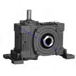
The EWDKO Series Double Worm Gear Reducer is the most integrated unit in the EW-family double-stage range: an IEC B5 motor flange eliminates the input coupling on one side, and two co-axial hollow bores exit from opposite output housing faces simultaneously, driven by a single shared worm wheel in the second stage. The result is three connection points — one input, two output bores — with zero couplings, zero coupling guards, and zero separate alignment steps at any of them. Two-stage worm reduction delivers 200:1 to 900:1, producing output speeds from 1.6 rpm to 7.25 rpm from a standard 4-pole motor. Both output bores rotate at exactly matched speed; the single worm wheel makes this synchronisation permanent rather than dependent on chain stretch, belt tension, or VFD algorithm timing. Stage pairs extend from 50-80 through 120-175 at input powers 0.18 kW to 2.2 kW. For Australian twin-stem gate valve mechanisms, bilateral solar tracker arrays, contra-rotating digester agitators, and precision co-axial slow-speed positioning systems, the EWDKO delivers what no alternative single-unit specification can provide at this reduction ratio range.
Technical Specifications — EWDKO Series Double Worm Gear Reducer
⚠️ Critical: Rated Torque Is the Combined Total Across Both Bores
Both EWDKO output bores share one worm wheel. If each driven shaft requires T Nm, select a stage pair rated for 2T combined output torque. Treating the rated torque as a per-bore figure when both bores are loaded simultaneously results in 2× overload on the second-stage worm wheel — the most common EWDKO specification error.
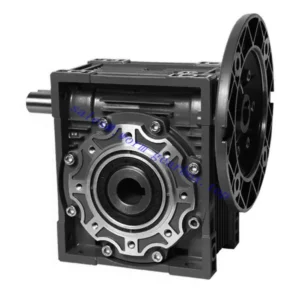
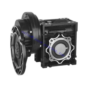
Input: IEC B5 Flange — Motor Direct
Motor bolts to IEC B5 flange — no input coupling, no motor base, no coupling guard. Motor shaft and first-stage worm shaft co-axial at 0.05 mm TIR by machined datum.
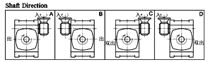
Output: Co-Axial Dual Hollow Bores — Both Faces
Two bores on the same rotational axis exit from opposite output faces. Both rotate at exactly matched speed from one worm wheel. Both driven shafts seat directly into bores — no output couplings.
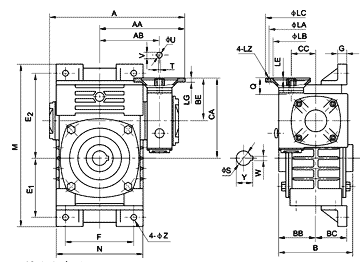
| Stage Pair | Power (kW) | Overall Ratio | A (mm) | B (mm) | BB (mm) | Flange LZ (mm) | Input Q (mm) | Output S (×2) | Key W×Y |
|---|---|---|---|---|---|---|---|---|---|
| 50–80 | 0.18 | 200–900 | 314 | 144 | 70 | 140 | 25 | Ø35×2 | 10 |
| 60–100 | 0.37 | 200–900 | 363 | 175 | 90 | 160 | 35 | Ø40×2 | 12 |
| 70–120 | 0.37/0.75 | 200–900 | 429 | 200 | 100 | 160/200 | 35/45 | Ø45×2 | 14 |
| 80–135 | 0.75/1.5 | 200–900 | 505 | 212 | 110 | 200 | 45 | Ø60×2 | 18 |
| 100–155 | 1.5 | 200–900 | 565 | 312 | 140 | 200 | 55 | Ø70×2 | 20 |
| 120–175 | 2.2 | 200–900 | 635 | 334 | 150 | 250 | 65 | Ø80×2 | 22 |
0.18–2.2 kW
IEC B5 Flange Input
Dual Co-Axial Hollow Bores
Double Self-Locking
200:1–900:1
EWDKO Position in the E-Family — Maximum Integration at Ultra-High Ratio
| Unit | Input | Output | Max Ratio | Couplings |
|---|---|---|---|---|
| EA/FCEA | Through-shaft or IEC flange | Solid shaft — 1 face | 900:1 | 1 (output) or 0 |
| EWA | Through-shaft (either side) | WA hollow bore — 1 face | 900:1 | 1 (input coupling) |
| EDA | IEC B5 flange | WA hollow bore — 1 face | 900:1 | 0 |
| EWDKO ← This Unit | IEC B5 flange | Dual co-axial hollow bores — 2 faces | 900:1 | 0 — three-end direct |
Six Advantages of the EWDKO for Ultra-High-Ratio Twin-Shaft Australian Drives
Three-End Zero Couplings at 200–900:1
IEC motor bolts to input flange — no input coupling. Each driven shaft slides into its hollow bore — no output couplings. Three connection points, zero coupling bodies, zero coupling guards, zero alignment procedures. In enclosed actuator housings, sealed digester head penetrations, and remote outdoor tracker installations, eliminating all coupling bodies from the installation envelope simplifies both mechanical design and safety compliance obligations.
Exact Co-Axial Synchronisation — Hardware Guaranteed
Both bores share one worm wheel — the 1:1 speed ratio between them is exact, permanent, and physically impossible to drift. At 1.6–7.25 rpm output, any timing error between co-axial shafts becomes immediately visible as mechanical misalignment. The EWDKO makes drift impossible by sharing one wheel between both bores rather than relying on chain, belt, or VFD algorithm synchronisation that accumulates error over time.
Double Self-Locking — Both Bores Held on Power-Off
Both worm stages self-lock simultaneously. Both driven shafts are locked against back-drive from either bore on power-off — without any external brake. For twin-stem gate mechanisms where both stems must hold simultaneously against flow-induced torque, this double self-locking delivered through both bores simultaneously provides positive mechanical hold at both outputs without any electrical or hydraulic locking system.
Replaces Two EDA Units + Synchronisation Mechanism
Achieving co-axial twin slow-speed hollow-bore drives with EDA units requires two complete EDA housings, two IEC motors, two VFDs, plus an inter-unit synchronisation shaft, coupling, and bearing support. The EWDKO replaces all of this with one housing, one motor, one VFD, zero synchronisation hardware, and two oil fill points within one unit. The hardware reduction is substantial in both cost and maintenance scope.
One Motor + One VFD Controls Both Output Speeds
One motor and one VFD controls both output bore speeds simultaneously. Both bores change speed proportionally when the VFD frequency changes; the 1:1 ratio between them is preserved at all VFD frequencies. Two separate EDA units with two VFDs require synchronisation programming and still have algorithm-dependent timing accuracy. The EWDKO provides hardware-guaranteed synchronisation that cannot be disrupted by control logic, communication delay, or VFD parameter drift.
120-175 Stage Pair — Ø80 mm Dual Bore at 2.2 kW
The EWDKO 120-175 with dual Ø80 mm bores at 2.2 kW input covers large-diameter co-axial shaft drives at ultra-high ratios. At 600:1 with 2.2 kW input and combined efficiency ≈ 50%, the combined theoretical output torque from both bores exceeds 5,500 Nm — covering large twin-stem gate valve mechanisms and heavy bilateral solar tracker arrays from one IEC motor and one VFD.
Applications — Ultra-High-Ratio Co-Axial Twin-Shaft Drives in Australian Plant
- 🌊 Twin-Stem Gate Valve and Penstock Mechanisms (high ratio worm gearbox)EWDKO 80-135 to 120-175 at 400:1–600:1 with both bore faces driving co-axial gate valve stems simultaneously. Both stems receive exactly matched force — no differential stem advance that racks or jams the gate. IEC motor bolts directly to input flange. Both stems self-lock on power-off without any separate brake or hydraulic hold. In large Australian water infrastructure penstocks where twin-stem mechanisms are standard for gates above 500 mm diameter, the EWDKO provides the most compact and zero-coupling twin-stem actuator available.
- 🧪 Contra-Rotating Digester Agitators — Gas-Tight Head PenetrationsEWDKO 60-100 to 100-155 at 300:1–500:1 for biogas and anaerobic digestion vessels where two contra-rotating impeller shafts entering from opposite vessel ends provide uniform mixing. Both impeller shafts seat in their respective EWDKO bores; the IEC motor and housing mount on the vessel lid. Zero coupling bodies anywhere in the drive eliminates all rotating coupling body hazard zones from the gas-tight lid penetration, reducing compliance obligations to the bore seals only.
- ☀️ Bilateral Solar Tracker Arrays — Central Drive PodEWDKO 60-100 to 80-135 at 500:1–800:1 for bilateral solar tracker arrays where one central EWDKO drives the left and right panel frame sections from its two output bores. Both panel sections receive exactly matched rotation; wind-induced frame flex does not cause differential torque on the worm wheel — both sides present the combined torque as a single load. Self-locking holds both panel sections at tracking angle throughout the night without any latch, brake, or holding relay.
- 🌾 Precision Twin Co-Axial Agricultural MeteringEWDKO 50-80 to 70-120 at 200:1–400:1 for precision planting implements where two co-axial metering shafts must rotate at exactly matched ultra-low speed for uniform bilateral seed placement. IEC flange allows direct connection to a tractor-mounted electric drive or compact BLDC motor; dual hollow bore outputs shaft-mount directly onto the implement’s bilateral metering rollers. For PTO-input agricultural variants, refer to agricultural PTO shaft integration resources for adaptor sizing.
- 🏭 Co-Axial Industrial Positioning — OEM AutomationEWDKO 70-120 at 400:1–600:1 for OEM industrial positioning mechanisms where a central driven axis must be actuated from both ends simultaneously without torsional wind-up differential. Injection moulding clamp mechanisms, precision press ram drives, and large-format motion table screw drives requiring co-axial twin-input ultra-low-speed drive are all applications where the EWDKO provides the required twin-input drive without a secondary synchronisation mechanism. Further guidance on industrial gearbox applications in Australian automation is available at gearboxagricultural.com.
Drive Accessories and Component Selection for the EWDKO
Motor Power — Combined Bore Load
Motor power must cover the combined torque from both bores: P_input = (T₁ + T₂) / (ratio × η). Using single-bore torque for motor sizing results in thermal overload during normal combined operation. This is the most common EWDKO commissioning error — always calculate from combined bore load.
Dual Shrink Discs — Both Bores
Both output bores require individual shrink discs for all EWDKO stage pairs 70-120 and above. Torque both discs in cross-pattern sequence simultaneously to maintain symmetric clamping pressure on both bore faces. Asymmetric clamping can generate lateral force on the second-stage worm wheel affecting bearing pre-load.
PAO Synthetic Oil — Both Stages
Two separate oil fill points — one per stage. For continuous duty at ratios ≥ 400:1 in 40°C+ Australian ambient, PAO synthetic ISO VG 220 in both stages extends the thermal ceiling by 10–15% and the service interval to 5,000 hours. The combined load from both bores increases first-stage heat generation vs. single-bore EDA at the same power.
Torque Arm — Combined Reaction + Weight
Torque arm must resist combined reaction torque (T₁ + T₂) plus gravitational moment of motor plus reducer assembly. At EWDKO 120-175 with motor, combined assembly may exceed 100 kg — always specify torque arm for the combined load, not reaction torque alone.
Thermal — Combined Load Assessment
The combined load from both bores increases heat generation versus an equivalent EDA. Thermal rating must be verified at the combined input power, not single-bore power. Submit combined input power, ratio, duty cycle, and Australian ambient temperature to the technical team before finalising specification.
Oil Orientation — Vertical Bore Config
Non-standard orientation (vertical bore axis for gate valve stem drives) requires orientation-specific oil fill levels for both stages independently. Submit your installation orientation drawing to the technical team before commissioning — oil starvation in the second stage under vertical bore orientation is the leading failure cause in gate actuator EWDKO installations.
Maintenance Schedule — EWDKO Series
| Interval | Task | EWDKO Dual-Bore Note |
|---|---|---|
| First 500 hr | Flush both stages; both shrink discs cross re-torque; flange bolt check | Inspect both bore faces for fretting symmetry — asymmetric fretting indicates unequal shrink disc clamping; re-torque the weaker disc before continuing |
| 2,500 hr | Oil change both stages; all seals; both shrink discs; flange face gasket | Four shaft penetrations (two bores + IEC flange bore) — inspect all four seal faces for oil weep at each service |
| 5,000 hr | Remove both bores; bore zone inspection; inter-stage bearing; both bore seals | Compare bore diameter at both faces — differential wear between bore 1 and bore 2 indicates unequal loading; investigate root cause before reassembly |
| If one bore jams | Full second-stage inspection; both bore zones before return to service | Full motor torque concentrates at jammed bore — inspect both bore zones and second-stage worm wheel bronze surface before returning either bore to service |
 For EWDKO combined torque calculations, stage pair selection for your specific twin-shaft load profile, dual shrink disc specification, thermal rating assessment, and oil orientation guidance for vertical bore gate valve installations, the engineering team at our worm gearbox technical portal provides full application-specific support. Submit your two driven shaft diameters, per-shaft torque requirements, overall ratio, and ambient temperature via the technical enquiry page.