Description
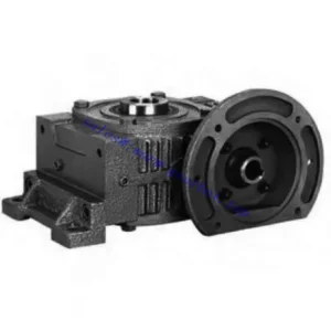
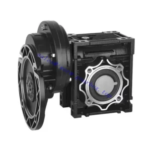
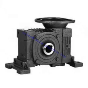
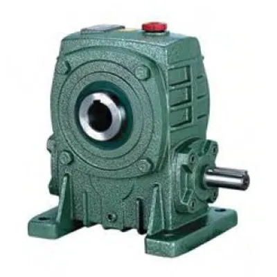
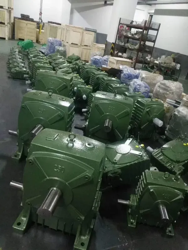
The KA Series Single Standard Worm Gear Reducer — designated WPKA — is the hollow-bore output variant within the WPA dimensional family. Rather than presenting a solid output shaft stub, the WPKA output bore passes completely through the worm wheel hub, accepting the driven shaft directly. This shaft-mount arrangement eliminates the output coupling, coupling guard, and key-fit alignment procedure that solid-shaft reducers require, replacing them with a single keyed bore and a locking element. The result is a compact worm gearbox that sits directly on the driven machine shaft — shorter in the output direction, lighter in total assembly weight, and simpler to maintain than any comparable solid-shaft configuration. Covering sizes 50 through 200 with standard gear ratios of 10:1 to 60:1, the WPKA suits every application where the driven shaft can act as the reducer’s mounting point rather than a downstream connection target.
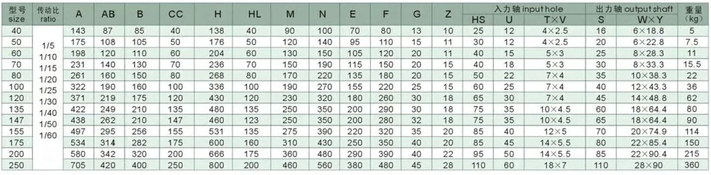
Technical Specifications — KA Series (WPKA) Hollow Bore Worm Reducer
| Size | Ratio | A (mm) | AB (mm) | B (mm) | H (mm) | HL (mm) | Output Bore S (mm) | Weight (kg) |
|---|---|---|---|---|---|---|---|---|
| 50 | 1/10–1/60 | 175 | 105 | 107 | 180 | 50 | Ø20 | 7 |
| 60 | 1/10–1/60 | 195 | 120 | 117 | 210 | 60 | Ø25 | 10.5 |
| 70 | 1/10–1/60 | 234 | 140 | 131 | 243 | 70 | Ø30 | 14.5 |
| 80 | 1/10–1/60 | 264 | 160 | 144 | 273 | 80 | Ø35 | 22 |
| 100 | 1/10–1/60 | 322 | 190 | 175 | 340 | 100 | Ø40 | 36 |
| 120 | 1/10–1/60 | 385 | 230 | 200 | 405 | 120 | Ø45 | 63 |
| 135 | 1/10–1/60 | 435 | 260 | 212 | 455 | 135 | Ø60 | 80 |
| 155 | 1/10–1/60 | 507 | 302 | 312 | 490 | 135 | Ø70 | 114 |
| 175 | 1/10–1/60 | 550 | 325 | 334 | 565 | 160 | Ø80 | 150 |
| 200 | 1/10–1/60 | 670 | 350 | 346 | 625 | 175 | Ø85 | 218 |
Input Shaft Dimensions — Solid Shaft Input (WPKA)
| Size | Input HS (mm) | Input Bore U (mm) | Key T×V (mm) | Output Key W×Y (mm) |
|---|---|---|---|---|
| 50 | 30 | 12 | 4×2.5 | 6×22.8 |
| 60 | 40 | 15 | 5×3 | 8×28.3 |
| 70 | 40 | 18 | 5×3 | 8×33.3 |
| 80 | 50 | 22 | 7×4 | 10×38.3 |
| 100 | 50 | 25 | 7×4 | 12×43.3 |
| 120 | 65 | 30 | 7×4 | 14×48.8 |
| 135 | 75 | 35 | 10×4.5 | 18×64.4 |
| 155 | 85 | 40 | 10×4.5 | 20×74.9 |
| 175 | 85 | 45 | 12×4.5 | 22×85.4 |
| 200 | 95 | 50 | 12×4.5 | 22×89.4 |
Ratio 10:1 – 60:1
Hollow Bore Output Ø20–85mm
Solid Shaft Input
Foot Mount (WPA Frame)
Shaft-Mount Installation
The Hollow Bore Advantage: What Disappears When You Remove the Output Shaft
The engineering case for hollow bore output is straightforward: every component between a solid-shaft reducer’s output stub and the driven shaft is a potential failure point. The WPKA eliminates the output coupling, coupling guard, and the requirement for parallel and angular alignment at the driven end. The driven shaft slides directly into the bore and is secured by a DIN 6885 parallel key and a locking element — the entire output connection is inside the reducer housing.
Shorter Driven-End Package Length
Eliminating the output shaft stub, coupling body, and coupling guard reduces the total axial length between reducer housing face and driven shaft bearing by 80–120 mm depending on size. On confined conveyor frames and tight plant layouts, this difference directly determines whether a retrofit drive fits without structural modification.
Reduced Overhung Load on Driven Shaft
With the reducer mounted directly on the driven shaft, the worm wheel output force transfers through the bore to the shaft at the bore midpoint — well within the reducer’s own bearing span. There is no cantilever moment arm adding to the driven shaft’s bearing loads, as would occur with a solid-shaft reducer and coupling arrangement.
No Coupling Alignment Required
A bore-mount reducer has no coupling to align. The driven shaft is the alignment reference — as long as the bore slides smoothly onto the shaft, concentricity is guaranteed by the H7/h6 bore-to-shaft fit. This eliminates the dial indicator alignment procedure that is the single most time-consuming step in conventional reducer installation.
Coupling Failure Mode Eliminated
Jaw coupling spider fatigue is among the most frequent planned maintenance items on Australian food and packaging lines. The WPKA removes this failure mode from the system entirely — the output bore connection has no elastomeric element to degrade, no jaw faces to wear, and no angular deflection to generate fretting corrosion on key surfaces.
Self-Locking at Ratios ≥ 30:1
The worm lead angle falls below the friction angle at 30:1 and above, making the WPKA non-back-drivable under static loads. A gravity-loaded conveyor or gate drive holds position on power-off without any additional brake — the bore connection transmits this holding torque directly into the driven shaft without the slip risk that external couplings can introduce under shock load.
Torque Arm Anchors Housing — No Separate Base
The WPKA housing carries both foot pads (standard WPA mounting) and a torque arm bracket point. In shaft-mount configuration, the foot pads are unused and the torque arm resists the reaction torque at the housing. This allows the reducer to be repositioned along the driven shaft without modifying the supporting structure — particularly useful in adjustable-centre drive arrangements.
Output Bore Engineering: Fit, Key, and Locking Element Selection
Bore Fit and Tolerance
The WPKA output bore is machined to H7 tolerance — a close clearance fit that centres the driven shaft within 0.015–0.025 mm radial clearance depending on bore diameter. This tolerance is tight enough to prevent rocking of the reducer on the shaft under dynamic loads, while still allowing manual disassembly without pressing equipment. The mating driven shaft should be machined to h6 or js6 tolerance at the bore contact length. For shafts machined to k6 (light interference), a hydraulic push-out tool will be required at disassembly — acceptable in permanent installations where removal is infrequent.
Keyway and Torque Transmission
The output bore keyway is broached to DIN 6885 Form A at the W×Y dimensions listed in the specification table. A parallel key seated in matching keyways on both bore and driven shaft transmits the output torque. For reversing or shock-load applications, a second key 180° opposite (keyed rather than single-keyed bore) can be specified as a custom option, increasing the torsional capacity of the shaft-bore connection without increasing the bore diameter. The key is a standard item; it must be fitted to zero backlash in the shaft keyway before the reducer is slid onto the shaft — a rocking key that contacts only on one face causes fretting corrosion in the bore over time.
Locking Elements and Shrink Disc Options
Three locking element options are available for the WPKA bore connection. A set screw through the bore hub is the standard, lowest-cost option — adequate for unidirectional constant-torque loads. For reversing or cyclic torque, a proprietary locking ring (shrink disc) that generates radial clamping force over the full bore length provides superior axial retention and eliminates the fretting risk associated with set screws under reversed loading. For hollow shafts or shafts where set screw indentation is unacceptable, a keyless interference bushing can be pressed into the bore and expanded onto the shaft — this option requires no machined keyway in the driven shaft.

Where Hollow Bore Output Solves Real Australian Engineering Constraints
The WPKA is most valuable where the driven shaft diameter, position, or axial length makes a solid-shaft reducer with coupling arrangement geometrically awkward. The following application archetypes represent its strongest fit:
- ⛓️ Conveyor Head Shaft Drive — Shaft-Mount Configuration
A WPKA slides directly onto the conveyor head shaft, secured by a torque arm to the conveyor frame. The worm reducer, motor, and all drive components sit on the conveyor shaft — the structure carries zero drive weight. Repositioning the reducer along the shaft to adjust sprocket position requires no structural modification. Size 80–120 at 20:1–40:1 covers the majority of Australian food processing and materials-handling conveyor applications. - 🌾 Grain Auger and Screw Conveyor Head Drive
Grain auger shafts in Australian bulk handling are typically 40–60 mm diameter and extend to the edge of the loading hopper — a solid-shaft reducer and coupling would require the motor to overhang the hopper, creating a cleaning and safety access problem. A WPKA bore-mounted directly on the auger shaft brings the motor parallel to the screw axis and eliminates the overhang entirely. Size 100–135 at 30:1–50:1 covers the standard 540 rpm PTO-equivalent electric motor speed range for bulk grain augers. - 🚿 Irrigation Channel Gate and Rack Actuators
Headstock-mounted gate actuators in Australian irrigation infrastructure use WPKA units where the gate shaft must be the mounting reference. The reducer sits directly on the gate lift shaft; a torque arm anchors the housing to the headstock frame. Salt-water spray environments on coastal irrigation infrastructure benefit from the WPKA’s sealed housing with no exposed coupling gap for moisture entry. - 🎡 Carousel and Turntable Centre-Shaft Drives
Rotating display units, product turntables, and carousel drives in Australian retail and exhibition environments use WPKA size 50–70 at 40:1–60:1 directly on the vertical centre shaft. The self-locking property at these ratios holds the turntable position when power is removed — preventing drift under uneven display loading — without any additional brake device. - 🔄 Fan and Blower Shaft Drives (Low-Speed Retrofit)
Where an existing large-diameter fan or blower shaft must be driven at very low speed (10–30 rpm output) from a standard 4-pole motor, a WPKA at 60:1 bore-mounted directly on the fan shaft eliminates the design challenge of supporting a solid-shaft reducer at the cantilevered end of a large-diameter shaft. The hollow bore centres itself on the shaft and the torque arm takes the reaction. - 🏗️ Winch and Hoist Drum Shaft Drives
Wire rope winches on Australian lifting equipment use WPKA size 120–155 at 20:1–40:1 mounted directly on the drum shaft. The worm self-locking provides the secondary load-holding function required by Australian Standards AS 1418 for manually suspended loads — with the hollow bore placing the reducer directly at the drum shaft, the drive envelope is minimised in the drum width direction.
PTO Shaft Integration, Torque Arm Configuration, and Drive Accessories
The WPKA input shaft is a standard WPA-class solid stub, accepting any standard motor or PTO coupling. The distinctive accessory requirements are on the output side — the hollow bore and torque arm combination replaces everything that a solid-shaft reducer’s output coupling system would require:
Agricultural PTO Shaft (Input)
A standard telescoping PTO shaft connects the tractor 540/1000 rpm output to the WPKA input stub. The input stub diameter and key dimensions follow the standard WPA series — match the PTO shaft’s implement-end yoke bore to the WPKA input shaft diameter at the selected size.
Torque Arm and Reaction Bracket
A torque arm bolted to the WPKA housing resists the reaction torque when the reducer is shaft-mounted. The arm anchors to a fixed structural point (conveyor frame, machine chassis) via a rubber-bushed end to absorb torsional shock without transmitting it to the structure. Torque arm length must be calculated so the bushed end force does not exceed the bracket attachment point’s rated load.
Shrink Disc Locking Element
A shrink disc replaces the set screw in applications with reversing torque or cyclic loading. It generates uniform radial clamping pressure over the full bore length, eliminating the point-contact stress that set screws create. Particularly recommended for WPKA units driving bidirectional conveyors or oscillating mixing paddles.
Motor and Input Coupling
The WPKA input accepts any standard motor via a jaw coupling and motor base (standard arrangement) or optionally via an IEC B5 flange adaptor plate for direct-mount motor integration. The flange adaptor is a non-standard option that effectively converts the WPKA into a WPKDA-class unit where both hollow bore output and motor flange input are present.
Thermal Sensor Port (Sizes 100+)
Sizes 100 and above feature an NPT sensor port for a PT100 temperature probe or bi-metallic switch. In shaft-mounted WPKA installations where the reducer sits on the driven shaft away from a direct view line, a thermal alarm connected to the motor starter provides the overtemperature protection that a manual housing temperature check cannot reliably deliver.
Pressure-Equalising Breather
In shaft-mounted installations where the WPKA orientation is non-standard (input horizontal, shaft vertical), the oil fill level must be adjusted and a pressure-equalising breather replaces the standard filler plug to prevent seal weeping caused by positive internal pressure under high duty-cycle continuous operation.
Shaft-Mount Installation: Step-by-Step for Reliable Service Life
Verify Shaft Diameter and Tolerance
Measure the driven shaft at the bore contact zone. Shaft diameter must match the WPKA bore S dimension within h6 or js6 tolerance. Surface roughness Ra ≤ 1.6 µm at the contact zone — a rough shaft surface causes fretting corrosion within the bore under cyclic loading.
Fit the Key and Lubricate the Shaft
Seat the parallel key to zero backlash in the shaft keyway. Lightly coat the shaft with clean gear oil — not grease, which prevents full bore insertion — and slide the WPKA onto the shaft. The unit should advance under hand pressure; if resistance is encountered, verify shaft diameter before applying force.
Position and Apply Locking Element
Position the WPKA at the correct axial location on the shaft. Apply the set screw or shrink disc locking element to the bore hub. For set screws: torque to the manufacturer’s specification over the key. For shrink discs: tighten bolts in a cross pattern to the rated clamping torque — do not fully tighten individual bolts sequentially.
Fit the Torque Arm
Connect the torque arm between the WPKA housing bracket and the fixed structural anchor point. The rubber bushing at the anchor end must be loaded in the correct direction — compression for constant-direction loads, or a double-acting bush for reversing torque. Check that the arm does not contact any rotating component across the full operational range of the driven machine.
Check Oil Level and Commission
WPKA units are pre-filled with ISO VG 220 mineral gear oil. Verify oil level at the sight glass in the installed orientation — non-standard orientations require adjusted fill levels. Run unloaded for 30 minutes, then at 50% load for 2 hours, monitoring housing temperature. Drain and refill at 500 hours (run-in flush); thereafter every 2,500 hours.
WPKA Selection: When Hollow Bore Is the Right Answer and When It Isn’t
The hollow bore configuration is not universally superior to solid-shaft. The WPKA is the correct choice when the driven shaft meets the following criteria — and a standard WPA or WPS is the correct choice when it does not:
| Condition | WPKA (Hollow Bore) | WPA / WPS (Solid Shaft) |
|---|---|---|
| Driven shaft diameter matches bore S dimension | ✓ Preferred | Viable with coupling |
| Driven shaft is too long for coupling attachment | ✓ Only viable option | ✗ Not possible |
| Output torque is reversing or cyclic | ⚠ Use shrink disc, not set screw | ✓ Standard coupling handles reversals |
| Drive must be repositionable axially during operation | ✗ Locking element must be released | ✓ Coupling allows axial float |
| Driven shaft diameter does not match any WPKA bore size | ✗ Custom bore required (4–6 weeks) | ✓ Coupling bored to any diameter |
| Driven shaft is the fixed structural reference | ✓ Preferred — no separate base needed | Requires separate motor base |
Maintenance Schedule — WPKA Hollow Bore Configuration
| Interval | Task | WPKA-Specific Note |
|---|---|---|
| First 500 hours | Oil drain and refill; torque arm bush inspection | Check bore contact zone for fretting marks — early sign of inadequate shaft fit or insufficient locking force |
| Every 2,500 hours | Full oil change; set screw or shrink disc re-torque | Torque arm bush wear check — replace bush if radial clearance exceeds 1 mm (transmits shock directly to structure) |
| Every 5,000 hours | Remove reducer from shaft; inspect bore and shaft contact zone | Look for fretting oxide (rust-brown powder) at the bore-shaft interface — indicates inadequate clamping; upgrade to shrink disc if found |
| At any seal replacement | Inspect input and housing seals; check input bearing radial play | WPKA has no output shaft seal — only input and housing static seals require periodic inspection |
For bore size confirmation, torque arm design assistance, and shrink disc selection for WPKA applications across Australia, the technical team at our worm gearbox engineering portal provides application-specific calculations and dimensional drawings. For agricultural shaft-mount drive integration including PTO-to-electric conversion projects, contact us via the technical enquiry page with your driven shaft specification.