Description
Technical Specifications — WK Series (and FCWK Variant)
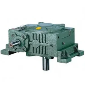
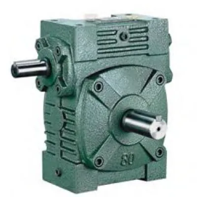
WK — Through-Shaft Input
Solid input shaft extends from both housing faces — motor couples to either side via jaw coupling. Unused side capped with blanking cap. Hollow bore output. Sizes 50–200, foot-mounted.
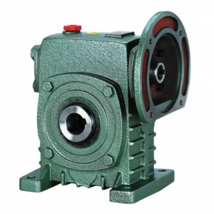
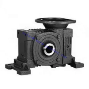
FCWK — IEC Flange Input
IEC B5 motor flange replaces through-shaft input. No input coupling, no coupling guard. Same hollow bore output. Motor bolts directly; fixes to one face. Sizes 50–200, foot-mounted.
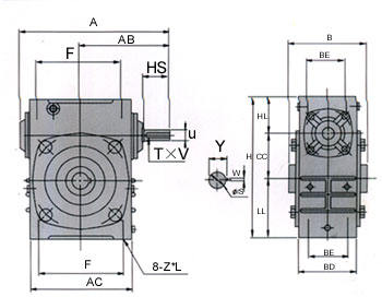
| Size | Ratio | A (mm) | B (mm) | AC (mm) | H (mm) | HL (mm) | Input HS (mm) | Output Bore S (mm) | Weight (kg) |
|---|---|---|---|---|---|---|---|---|---|
| 50 | 1/10–1/60 | 175 | 107 | 115 | 150 | 35 | 30 | Ø20 | 6 |
| 60 | 1/10–1/60 | 195 | 117 | 126 | 177 | 42 | 40 | Ø25 | 8.5 |
| 70 | 1/10–1/60 | 234 | 131 | 155 | 215 | 55 | 40 | Ø30 | 12.5 |
| 80 | 1/10–1/60 | 264 | 144 | 174 | 250 | 65 | 50 | Ø35 | 20 |
| 100 | 1/10–1/60 | 322 | 175 | 224 | 310 | 80 | 50 | Ø40 | 33 |
| 120 | 1/10–1/60 | 385 | 200 | 264 | 370 | 95 | 65 | Ø45 | 50 |
| 135 | 1/10–1/60 | 435 | 212 | 304 | 425 | 105 | 75 | Ø60 | 77 |
| 155 | 1/10–1/60 | 494 | 312 | 330 | 461 | 103 | 85 | Ø70 | 100 |
| 175 | 1/10–1/60 | 548 | 334 | 370 | 521 | 123 | 85 | Ø80 | 140 |
| 200 | 1/10–1/60 | 688 | 346 | 420 | 575 | 130 | 95 | Ø85 | 200 |
Ratio 10:1–60:1
W-Series Housing
Hollow Bore Ø20–85mm
WK: Through-Shaft Input
FCWK: IEC Flange Input
WK in the W-Family Bore Depth Hierarchy
The W family offers three hollow-bore depth grades at each size number. Understanding where the WK sits determines whether it is the right specification or whether the WKA (deeper bore, next article) is the correct selection:
| Variant | HL at Size 100 (mm) | Shock Tolerance | Best Application |
|---|---|---|---|
| WK / FCWK | 80 mm | Moderate (SF ≤ 1.5) | Smooth continuous loads; legacy W series shaft-mount retrofits |
| WA | 100 mm | Moderate (SF ≤ 1.75) | Standard shaft-mount applications; WP-family dimensional convention |
| WKA | 150 mm | High (SF ≤ 2.5) | Shock loads, auger stone strikes, screw conveyor axial thrust; W series footprint |
Selection guidance: The WK (HL = 80 mm at size 100) is the correct choice when the driven shaft load is smooth and continuous with no significant shock, and the W series dimensional convention is required — particularly when replacing an existing W series solid-shaft unit with a shaft-mount hollow-bore unit on the same machine without baseplate modification. For any shock loads, specify the WKA.
WK/FCWK Key Advantages
Size 200 — Largest W-Family Hollow Bore
The WK extends to size 200 with a Ø85 mm output bore and 200 kg unit weight — the largest hollow-bore specification available in the W family. No WP-series hollow-bore unit reaches this frame. For large conveyor head shafts and bulk handling equipment built around the W series convention, the WK200 is the only available hollow-bore option at this scale.
WK: Motor on Either Side
The WK through-shaft input allows the motor coupling to be placed on either side of the housing. In legacy W series equipment where structural elements constrain motor position, this flexibility eliminates the need to redesign the motor mounting bracket when retrofitting the shaft-mount configuration.
W-Series Footprint — No Baseplate Change
WK housing dimensions match the W series convention — A, B, H, and foot pad bolt pattern are identical to the W series baseline. When replacing a W series solid-shaft unit with a WK hollow-bore unit on the same machine, the baseplate, motor base, and coupling guard are the only components that change. The structural machine bay requires no modification.
Self-Locking at ≥ 30:1
Static self-locking at 30:1 and above holds the output bore stationary on power-off without a brake. In foot-mounted configuration with the shaft-mount bore engaged, the locking torque acts directly on the driven shaft through the bore connection. For gravity-loaded conveyors and gate actuators, this eliminates a separate braking device.
FCWK: Motor-Direct, Zero Input Coupling
The FCWK IEC B5 flange eliminates the input coupling and coupling guard — any IEC B5 motor of the correct frame bolts directly to the flange face. Motor shaft and worm shaft are concentric within 0.05 mm TIR. In OEM production, this saves 45–60 minutes of motor base fabrication and coupling alignment time per unit.
No Output Coupling — Shaft-Mount Direct
The hollow bore output eliminates the output coupling, coupling guard, and output alignment procedure. The driven shaft becomes the mounting reference — the WK/FCWK slides directly onto it and is retained by key and locking element. In wet-area and food-grade environments, this removes one coupling gap and one rotating guard surface from compliance obligations.
Application Environments — WK for Legacy Retrofit, FCWK for New Motor-Direct Builds
- 🔄 Legacy W Series Machine Shaft-Mount Retrofit (WK)
When an existing W series solid-shaft machine is upgraded to shaft-mount drive (eliminating the output coupling as part of a maintenance simplification programme), a WK replaces the W series unit: same baseplate, same motor, same motor coupling — only the output connection changes. Sizes 50–200 match the full W series range. - ⛓️ Conveyor Head Shaft Drives — Large Shaft Diameters (WK/FCWK)
Large conveyor head shafts at sizes 155–200 (Ø70–85 mm bore) in Australian bulk handling and mining are exclusively served by the WK/FCWK — no WP-series hollow-bore unit reaches these bore diameters. FCWK configuration at this scale eliminates the input coupling, which is a significant fretting and maintenance liability on the large-diameter input shafts of Class 3 and 4 conveyors. - 📦 OEM Packaging Machines — Motor-Direct Shaft-Mount (FCWK)
FCWK size 50–80 for packaging conveyor and metering drives where both the motor coupling (input) and the output coupling are eliminated. W series dimensional convention is preserved for OEM builders standardised on W series frame dimensions. No baseplate redesign required between motor-coupled W series and FCWK production generations. - 🌾 Agricultural Implement Electric Conversion (FCWK)
Tractor PTO-driven implements converted to electric motor drive use FCWK size 80–120 where the motor must flange-mount directly to the reducer and the bore seats on the existing implement shaft. The IEC B5 flange accommodates any standard electric motor; the W series housing fits the implement’s existing frame clearance envelope that was originally designed around the W series reducer. For PTO shaft sizing reference, see our PTO shaft technical resources. - 💧 Water Treatment and Irrigation Infrastructure (WK)
Gate actuators and paddle mixers in Australian irrigation infrastructure built around W series dimensional conventions use WK for shaft-mount output — the through-shaft input allows motor positioning to clear headstock structural members on either side. The sealed housing with hollow bore output presents no coupling gap for water ingress in flood-prone installations.
Drive Accessories and Input Integration
WK: Motor + Jaw Coupling
Standard jaw coupling to either WK input stub. Couple to the motor-access side; cap the other with the blanking cap and lip seal. Inspect both seals — the capped stub and the active input shaft seal — at every oil change interval.
FCWK: IEC B5 Motor — Frame Check Critical
Verify motor IEC frame against FCWK flange dimensions: Z×L foot bolt, BD/BE cross dimensions. Motor shaft length must not exceed T×V bore depth. Record the motor IEC frame on the plant maintenance schedule for remote-site replacement planning.
Output Bore Locking Element
Set screw for smooth continuous loads (WK HL = 80 mm provides moderate engagement). For any reversing or cyclic loads, specify a shrink disc — the WK’s shorter bore depth concentrates shock torque over a smaller key face area than the WKA, making shrink disc locking more important at the margin.
Torque Arm
In shaft-mount configuration, torque arm anchors housing against reaction torque. For FCWK, torque arm load includes motor weight moment — size accordingly. WK size 175 and 200 require heavy-duty torque arm with dual rubber bushes given the 140–200 kg combined reducer weight alone.
Oil and Breather
ISO VG 220 mineral gear oil standard fill. For sizes 175 and 200, verify fill level for the installed orientation — non-standard shaft-mount orientations at large frame sizes create significant oil redistribution. A pressure-equalising breather prevents seal weeping under positive housing pressure at high duty cycles.
WK: Blanking Cap — Dusty Environments
The WK unused input stub blanking cap is a critical seal in Australian agricultural and mining environments. Fit a secondary labyrinth dust cap over the standard blanking cap in dusty conditions. Inspect and replace the lip seal at every oil change — failed blanking cap seals are the leading cause of premature worm wheel wear in W-family units across Australian field service.
Maintenance Schedule — WK/FCWK
| Interval | Task | WK/FCWK Note |
|---|---|---|
| First 500 hours | Oil flush; bore fretting inspection; blanking cap check (WK) | WK shorter HL means earlier fretting indicator — rust-brown powder at bore face within first 500 hours signals inadequate locking force; upgrade to shrink disc immediately |
| Every 2,500 hours | Oil change; all seals; locking element re-torque | WK: replace blanking cap lip seal proactively — Australian dust and moisture conditions accelerate lip hardening faster than clean-environment service intervals suggest |
| Every 5,000 hours | Remove bore from shaft; bore and shaft contact inspection | WK HL = 80 mm means bore fretting progresses to bore widening faster than WKA at same torque — confirm bore diameter within 0.03 mm of original spec; replace housing if bore is out of round |
| FCWK motor replacement | Verify IEC frame and shaft length before ordering | Log motor frame on maintenance schedule at installation — at large sizes (155–200), motor frame errors cause multi-day delays on remote Australian sites |
For WK/FCWK size 175 and 200 procurement planning, dimensional cross-referencing with legacy W series equipment, bore locking element selection, and torque arm sizing at large frame weights, the engineering team at our worm gearbox technical portal provides application-specific support. Contact us via the technical enquiry page with driven shaft diameter, load torque, and ambient temperature for a confirmed selection recommendation.