Description
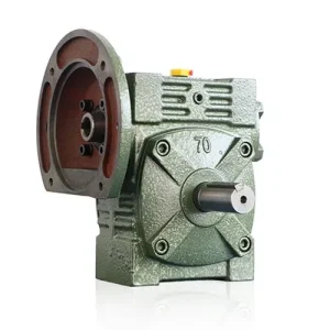
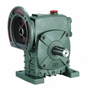
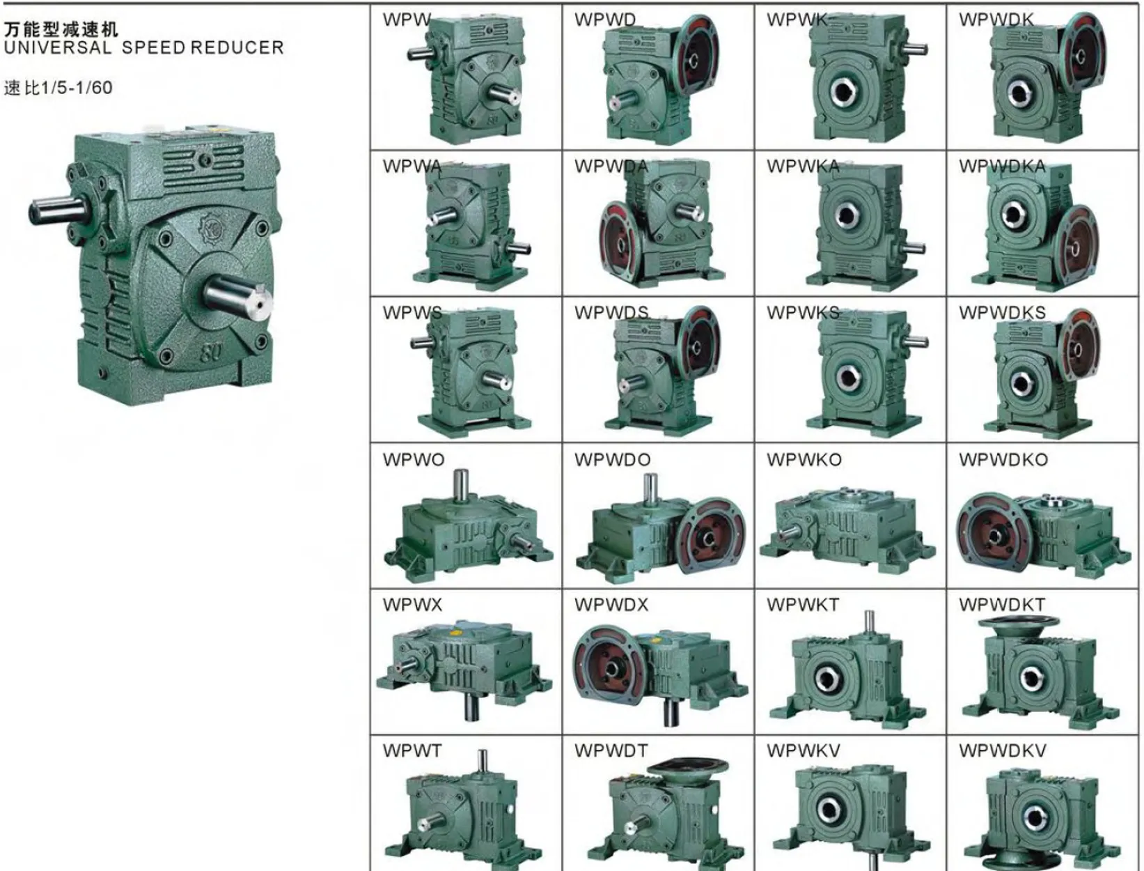
The DKS Series Single Standard Worm Gear Reducer — designated WPDKS — occupies the most demanding position in the WP hollow-bore family. Where the WPDKA combines a motor flange with the WPA-class bore depth, the WPDKS steps up to the WPS-class bore depth and tapered roller output bearings from size 80 onwards, while retaining the same IEC B5 input flange. The result is a high torque worm gearbox that removes both input and output couplings simultaneously and sustains the heavy overhung loads, axial shaft forces, and shock torques that a WPDKA cannot. Sizes 50 through 175, input powers to 7.5 kW, standard ratios 10:1 to 60:1 — this is the correct specification when the application genuinely needs motor-direct input and bore-mount output, but the driven shaft also carries chain, belt, or conveyor shock loads.
Technical Specifications — DKS Series (WPDKS) Worm Gear Reducer
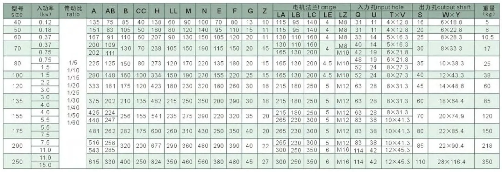
| Size | Power (kW) | Ratio | A (mm) | B (mm) | H (mm) | HL (mm) | Flange LA (mm) | Output Bore S (mm) | Weight (kg) |
|---|---|---|---|---|---|---|---|---|---|
| 50 | 0.18 | 1/10–1/60 | 155 | 107 | 180 | 130 | 115 | Ø20 | 8 |
| 60 | 0.37 | 1/10–1/60 | 170 | 117 | 205 | 150 | 130 | Ø25 | 10.5 |
| 70 | 0.37 / 0.75 | 1/10–1/60 | 206 | 131 | 235 | 175 | 130 | Ø30 | 17 |
| 80 | 0.75 / 1.5 | 1/10–1/60 | 232 | 144 | 265 | 200 | 165 | Ø35 | 26 |
| 100 | 1.5 | 1/10–1/60 | 266 | 175 | 327 | 250 | 165 | Ø40 | 38 |
| 120 | 2.2 / 3.0 | 1/10–1/60 | 340 | 200 | 388 | 300 | 215 | Ø45 | 60 |
| 135 | 3.0 / 4.0 | 1/10–1/60 | 375 | 212 | 445 | 350 | 215 | Ø60 | 85 |
| 155 | 5.5 | 1/10–1/60 | 442 | 312 | 483 | 390 | 265 | Ø70 | 120 |
| 175 | 7.5 | 1/10–1/60 | 465 | 334 | 550 | 435 | 265 | Ø80 | 150 |
IEC B5 Input Flange Dimensions — WPDKS
| Size | LZ (mm) | LB (mm) | Bolt | Input Q (mm) |
|---|---|---|---|---|
| 50 | 140 | 95 | M8 | 25 |
| 60 | 160 | 110 | M8 | 35 |
| 70 | 160/200 | 110/130 | M8/M10 | 35/45 |
| 80 | 200 | 130 | M10 | 45/55 |
| 100 | 200 | 130 | M10 | 55 |
| 120 | 250 | 180 | M12 | 65 |
| 135–155 | 250 | 180 | M12 | 65/85 |
| 175 | 300 | 230 | M12 | 85 |
0.18–7.5 kW
WPS-Class Bore Depth
IEC B5 Flange Input
Tapered Roller (Size 80+)
Hollow Bore Ø20–80mm
WPDKS vs WPDKA: The Critical Difference Shock Loads Expose
Both the WPDKA and WPDKS combine a motor flange with hollow bore output. The difference that matters under load is the bore depth (HL dimension). At size 100, WPDKA HL = 100 mm; WPDKS HL = 250 mm. This 2.5× increase in bore engagement length halves the key face pressure at a given output torque — the direct engineering reason why grain auger stone strikes, conveyor jam events, and cyclic shock loads destroy WPDKA keyways but leave the WPDKS intact.
WPS-Class Bore Depth — 2.5× More Key Engagement
The HL dimension follows the WPS family, not the WPA. At every size, the bore contact length is substantially longer than the WPDKA — distributing output torque across a greater keyway face area and lowering surface pressure below the fretting fatigue threshold even under shock loads.
Tapered Roller Bearings at Sizes 80+
Deep-groove ball bearings handle radial load only; tapered rollers sustain both radial and axial shaft forces. Screw conveyors, helical-cut driven elements, and belt drives with misalignment all generate axial thrust that destroys ball bearings in an WPDKA — the WPDKS handles this as a rated load condition from size 80 onwards.
Motor-Direct + Shaft-Mount — No Couplings Either End
Like the WPDKA, the WPDKS eliminates both the input coupling (via IEC B5 flange) and the output coupling (via hollow bore). The difference is structural capacity — the WPDKS delivers this zero-coupling convenience for applications where the driven shaft faces loads that would rattle a lighter unit to failure.
Self-Locking at Ratios ≥ 30:1
At 30:1 and above, the worm lead angle falls below the friction threshold and the bore output stays stationary on power-off. The WPS-class bore transmits this holding torque into the driven shaft with a contact area sufficient to resist the static load without bore fretting — a failure mode that undermines self-locking reliability in shallower bore configurations under sustained static load.
Maximum Axial Compactness — Zero Protrusions
Motor face to housing face is the reducer A dimension only. No coupling bodies, no shaft stubs, no guards. In conveyor head shaft retrofits where the existing bay has fixed axial clearance, eliminating two coupling body lengths can mean the difference between a straight replacement and a structural bay modification.
IEC Motor Interchangeability
Any IEC B5 motor of the correct frame drops straight onto the WPDKS flange — no reboring, no baseplate modification. On remote Australian sites where motor replacement must happen quickly from whatever is in the electrical store, this interchangeability is an operational requirement, not a convenience.
Engineering Construction: Three Precision Interfaces, One Casting
Bore Geometry and Hub Wall Thickness
The WPDKS bore passes through the worm wheel hub. The WPS housing geometry provides more external hub wall thickness than the WPA/WPDKA equivalent — this is the structural prerequisite for the longer HL bore depth. At size 100, the WPDKS hub wall above the bore is approximately 28 mm, versus 18 mm in the WPDKA. This additional material is what allows the bore to extend to 250 mm depth without the hub wall stress concentration that would cause fatigue cracking under repeated shock loading at the bore-shaft key contact.
Flange Face Machining — Single Datum Setup
The IEC B5 input flange, the worm shaft bore, and the output hollow bore are all finish-machined in a single setup from a common datum. This is the only manufacturing method that guarantees the motor shaft and worm shaft are truly co-axial — a prerequisite for the claimed input concentricity of 0.05 mm TIR. Reducers where the flange is machined separately from the gear housing in different setups cannot achieve this tolerance reliably across a production run, and the misalignment that results introduces a cyclical input bearing load that reduces input bearing life.
Worm Gear Set — Same Specification as WPDS
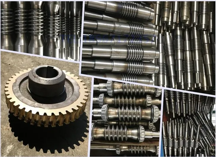
The worm shaft is 42CrMo4 alloy steel, case-hardened and ground to Ra ≤ 0.8 µm on the tooth flanks. The worm wheel is centrifugally cast phosphor-bronze, pressed and keyed onto a cast iron hub. Both conform to DIN 3975 quality class 7 — the same gear set that drives the WPDS solid-shaft variant. The lubrication system is oil-bath with ISO VG 220 mineral gear oil pre-filled; worm input speed is capped at 1,450 rpm (standard 4-pole motor). This limit is absolute — do not programme a VFD above 50 Hz on a 4-pole motor driving a WPDKS.

Applications Where the WPDKS Is the Technically Correct Specification
- 🌾 Grain Auger Head Shaft Drives — Stone Strike Protection
A WPDKS135 at 30:1 on a Ø60mm auger shaft handles the continuous torque plus repeated 3–5× peak stone-strike events without keyway fretting. The motor flanges directly to the reducer; the reducer bore-mounts on the auger shaft. No coupling gap for grain dust accumulation; no coupling spider to replace at harvest-end service. - ⛏️ Mining Conveyor Belt Head Drum — Jam-Load Resilience
Underground and open-cut conveyors in Australia experience emergency stops and belt jam events that impose shock torques of 3–5× rated continuous torque on the head shaft. The WPDKS bore depth and tapered roller bearings absorb these events. The motor flanges directly, removing the coupling that is the first failure point in conventional head-shaft drive assemblies. - 🏭 Plastics Extruder Screw Drives
Extruder screws carry both high torque and axial thrust from barrel pressure. A WPDKS bore-mounted on the extruder screw shaft handles both simultaneously. The tapered roller output bearings sustain the axial component without fatigue; the deep bore sustains the torsional reversals at purge and startup without keyway cracking. - 🌊 Screw Conveyor Drives for Heavy Materials
Cement, mineral sands, and tailings slurry screw conveyors generate sustained axial thrust from the screw geometry. WPDKS size 100–135 handles the combined radial and axial output load that would destroy an WPDKA’s ball bearings within months. The motor flange eliminates the coupling that requires alignment re-verification every time the screw is removed for maintenance. - 🔩 Winch and Hoist Drum Drives — AS 1418 Compliance
The WPDKS self-locking at 30:1+ provides the secondary load-holding function for gravity-loaded hoists. The deep bore distributes static holding torque over a large key engagement area, preventing the bore fretting that undermines self-locking reliability in shallow-bore configurations under sustained static loading of heavy suspended loads.
PTO Integration and WPDKS Drive Components
The WPDKS input accepts an IEC motor, a PTO shaft with flange adaptor, or a hydraulic motor adaptor. Each input pairing has specific accessory requirements when combined with the WPDKS’s shaft-mount bore output:
IEC B5 TEFC or Force-Ventilated Motor
Standard 4-pole TEFC at 1,450 rpm for most applications. Force-ventilated (IC416) motor required for VFD operation below 25 Hz. Motor shaft length must not exceed WPDKS input bore depth T×V — a bottomed-out shaft prevents flange face seating and introduces angular misalignment.
PTO Shaft with Flange Adaptor + Slip Clutch
For tractor PTO input, a flange-end adaptor plus a calibrated friction slip clutch (set at 1.5× rated input torque) protects the worm gear set from agricultural shock events. Critical for grain auger and rotary tiller applications where rock strikes can generate instantaneous torques well above the continuous rating.
Shrink Disc — Mandatory for Shock Applications
A shrink disc replaces the set screw for all shock-load WPDKS applications. Uniform radial clamping over the full bore depth prevents the progressive set screw loosening that repeated shock torques cause — a failure mode that reinstates the fretting risk the deeper bore was designed to eliminate.
Heavy-Duty Torque Arm (Dual Bush)
The torque arm must carry the combined weight of motor + reducer as a gravitational moment, plus the reaction torque. For WPDKS sizes 100 and above with a typical IEC motor, a dual rubber-bushed heavy-duty arm is specified — single-bushed arms can fatigue at the anchor point under the combined dynamic and static loading of this configuration.
Thermal Sensor Port (Sizes 100+)
Sizes 100 and above include an NPT sensor port on the housing for a PT100 or bi-metallic switch. In heavy-duty shaft-mount applications where the reducer is not in direct sight of operators, a SCADA-connected temperature alarm provides the only reliable overtemperature protection — visual housing inspection is impractical when the unit is bore-mounted on a running shaft.
Synthetic PAO Oil (High-Duty Continuous)
For WPDKS units at ratios 40:1+ in continuous duty at 40°C+ Australian ambient, PAO synthetic ISO VG 220 recovers 10–15% thermal headroom versus mineral oil and extends the oil change interval to 5,000 hours — a measurable maintenance cost reduction for large conveyor drive fleets in Australian mining and bulk handling.
Selecting the Correct WPDKS: Four Checks Before Confirming the Order
Combined Output Torque with Service Factor
T_required = T_continuous × SF (1.5 for moderate shock, 2.0–2.5 for heavy shock). Select WPDKS size whose rated output torque at the chosen ratio exceeds T_required. Do not use motor nameplate torque as the only reference — the worm mesh efficiency at the selected ratio must be included.
Driven Shaft Diameter vs Bore S Dimension
The driven shaft must match the WPDKS bore S dimension within H7/h6 tolerance. If the shaft is non-standard, confirm whether a custom bore is more cost-effective than re-machining the shaft — for single-unit requirements, shaft remachining is almost always faster and cheaper than a 4–6 week custom bore lead time.
Thermal Rating at Actual Ambient
At 40°C ambient (Australian summer shed), derate the catalogue P_th by ~8% for each 10°C above 20°C. At 40:1 ratio in continuous duty, the thermal limit governs in the majority of WPDKS size selections — verify this before placing the order. Consider synthetic oil if the thermal limit is marginal.
Motor IEC Frame vs WPDKS Flange Table
Cross-reference motor flange register diameter, bolt circle, and shaft length against the WPDKS flange table. Record the motor frame on the plant maintenance schedule — when a motor must be replaced at 2 a.m. during a production breakdown, a wrong frame motor on-site extends downtime by days.
Maintenance Schedule — WPDKS Heavy-Duty Configuration
| Interval | Task | WPDKS-Specific Note |
|---|---|---|
| First 500 hours | Oil flush and refill; shrink disc re-torque | Inspect bore-shaft zone for fretting powder — early sign of inadequate clamping or shaft surface roughness |
| Every 2,500 hours | Oil change; all seals; torque arm bush inspection | Tapered roller bearing grease nipple (sizes 80+): NLGI Grade 2 EP grease, avoid over-greasing |
| Every 5,000 hours | Remove from shaft; bore, shaft, motor bearing inspection | Check tapered roller radial play: >0.08 mm warrants replacement; shock applications may require earlier inspection |
| After any jam event | Full inspection: worm wheel, bore, shrink disc | Even one 5× peak torque event can initiate keyway fatigue crack in the bore — inspect before return to service regardless of apparent damage |
| Motor replacement | Verify replacement IEC frame code | Log original motor frame on both the gearbox label and plant maintenance schedule |
For bore size confirmation, IEC motor frame cross-referencing, torque arm design calculations, and technical drawings for the DKS series across Australian mining, agricultural, and processing industry applications, the engineering team at our worm gearbox technical portal provides application-specific support. Contact us via the technical enquiry page with your motor specification and driven shaft dimensions for a selection confirmation with lead-time and pricing.