Description
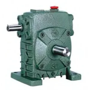
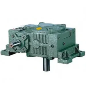
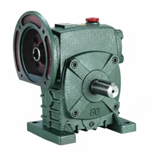
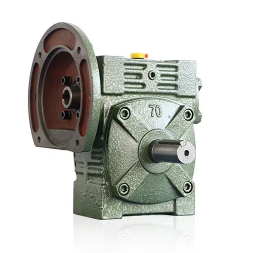
The WD Series Worm Gear Reducer — catalogued under the FCWD designation — is the motor-flange input member of the W family, adding an IEC B5 input flange to the W series’ solid output shaft configuration. Where the standard W series accepts motor input through a separate jaw coupling and motor base, the FCWD presents a machined flange face concentric with the worm shaft axis — the motor bolts directly to it, eliminating the coupling, coupling guard, and alignment procedure on the input side. The W series’ substantial output shaft section, deeper bearing span, and larger housing height are retained fully, making the FCWD the correct specification when motor-direct input is required alongside the W series’ solid-shaft output overhung load capacity. Covering sizes 50 through 155 with input powers from 0.18 kW to 5.5 kW and ratios 10:1 to 60:1, the FCWD bridges the gap between the compact WPDA (WP-family flange input, lighter output section) and the heavier W series standalone solid-shaft units where a separate motor base would otherwise be required.
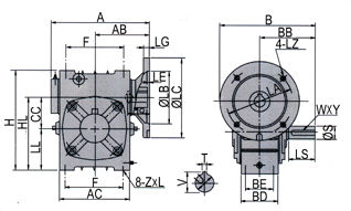
Technical Specifications — WD Series (FCWD) Worm Gear Reducer
| Size | Power (kW) | Ratio | A (mm) | B (mm) | H (mm) | HL (mm) | Flange LA (mm) | Output LS (mm) | Weight (kg) |
|---|---|---|---|---|---|---|---|---|---|
| 50 | 0.18 | 1/10–1/60 | 165 | 175 | 150 | 115 | 115 | 40 | 7 |
| 60 | 0.37 | 1/10–1/60 | 185 | 190 | 177 | 135 | 130 | 50 | 11 |
| 70 | 0.37 / 0.75 | 1/10–1/60 | 209 | 210 | 215 | 160 | 130 | 60 | 14 |
| 80 | 0.75 / 1.5 | 1/10–1/60 | 242 | 240 | 250 | 185 | 165 | 65 | 22 |
| 100 | 1.5 | 1/10–1/60 | 310 | 263 | 310 | 230 | 165 | 75 | 36 |
| 120 | 2.2 / 3.0 | 1/10–1/60 | 361 | 310 | 370 | 275 | 215 | 85 | 63 |
| 135 | 3.0 / 4.0 | 1/10–1/60 | 412 | 335 | 425 | 320 | 215 | 95 | 80 |
| 155 | 5.5 | 1/10–1/60 | 442 | 402 | 461 | 358 | 265 | 110 | 114 |
IEC B5 Input Flange — FCWD
| Size | LZ (mm) | LB (mm) | Bolt | Input Q (mm) | Z×L |
|---|---|---|---|---|---|
| 50 | 140 | 95 | M8 | 25 | M6×20 |
| 60 | 160 | 110 | M8 | 35 | M8×20 |
| 70 | 160/200 | 110/130 | M8/M10 | 35/45 | M10×25 |
| 80 | 200 | 130 | M10 | 45/55 | M12×28 |
| 100 | 200 | 130 | M10 | 55 | M12×30 |
| 120 | 250 | 180 | M12 | 65 | M14×32 |
| 135 | 250 | 180 | M12 | 65 | M16×35 |
| 155 | 300 | 230 | M12 | 85 | M16×35 |
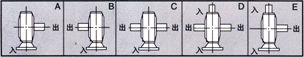
0.18–5.5 kW
IEC B5 Flange Input
W-Series Output HL DepthSolid Shaft Output Foot + Flange Mount
FCWD vs WPDA: Why the W-Series Output Section Commands a Premium
The FCWD and WPDA both combine an IEC B5 flange input with a solid shaft output — but the output section geometry is fundamentally different. The FCWD carries the W series’ deeper HL bearing span and longer output shaft extension. At size 100, FCWD HL = 230 mm versus 100 mm in the WPDA. This deeper output bearing support directly increases the permissible overhung load from chain sprockets and belt pulleys positioned at the shaft tip — the critical constraint in most Australian conveyor and material handling applications where chain drives are mounted away from the housing face.
Deeper Output Bearing Span — Higher OHL
The W series HL dimension provides a longer output shaft bearing span than the WP equivalents at each size. OHL capacity scales with the cube of bearing span — the FCWD’s output shaft tip carries substantially more radial load from chain and belt drives than the WPDA can sustain at the same size number.
Factory-Precision Motor Concentricity
Motor shaft and worm shaft are co-axial within 0.05 mm TIR — machined in a single setup from a common datum. No coupling misalignment, no cyclic input bearing loading from angular error, no coupling spider fatigue. The FCWD removes these three failure mechanisms from the drivetrain simultaneously.
IEC Motor Interchangeability
Any IEC B5 motor of the correct frame drops directly onto the FCWD flange — no re-boring, no baseplate revision, no new coupling selection. In remote Australian sites where motor replacement must be sourced locally from electrical wholesaler stock, this interchangeability avoids critical spares stocking.
Faster Assembly vs Separately Coupled W Series
Eliminating the motor base, input coupling, and coupling guard reduces installation time by 45–90 minutes per unit. In OEM machine production, this simplification is a direct manufacturing cost saving. In field replacement, it reduces planned shutdown window on a like-for-like FCWD installation.
Compact Axial Package — No Input Protrusions
Motor face sits flush against the flange face — no motor base, coupling body, or guard protrudes from the input side. In structural bays where axial clearance on the input side is limited, this reduces the required bay length by the coupling body depth (typically 80–140 mm depending on size) and the motor base height.
Self-Locking at ≥ 30:1
Effective static self-locking at ratios 30:1 and above — position held on power-off without a brake. The W series output shaft section transmits this holding torque with a longer bearing span than the WP equivalents, which is relevant for gravity-loaded conveyor applications where the output shaft must sustain both the running torque and the sustained static load.
Engineering Construction: FCWD vs WPDA — The Output Section Difference
Output Shaft Section: W Series Geometry
The FCWD output shaft carries the W series HL dimension — the depth of the output bearing housing measured along the worm wheel shaft axis. At size 100, FCWD HL = 230 mm; WPDA HL ≈ 65 mm. This 3.5× greater bearing span is the mechanical origin of the FCWD’s higher permissible overhung load. Since the bending moment on an output shaft bearing from an overhung sprocket or pulley is proportional to the distance from the load to the bearing, and the bearing lifetime is inversely proportional to the cube of the load, the FCWD bearing at size 100 sustains a radial load that would consume the WPDA bearing’s L10 life over 40× faster at the same sprocket position.
Flange Input Machining — Shared Datum with Output
The IEC B5 input flange is finish-machined concentric with the worm shaft bore in a single fixture setup. This single-datum machining is the only reliable method for achieving the claimed 0.05 mm TIR motor concentricity in production. Motor shaft → worm shaft → worm wheel → output shaft is an unbroken precision kinematic chain, with no cumulative alignment error introduced by separate motor base machining tolerances or field alignment procedures.
AC Dimension — W Series Housing AC Characteristic
The FCWD introduces the AC dimension (overall housing length including the flange extension) which is larger than the A centre-distance dimension. At size 100, A = 310 mm but AC = 263 mm extension adds to the flange face — the total installed length from flange face to output shaft end is AC + LS. This dimension is the critical one for bay length clearance checks, not the A dimension alone — a point frequently missed in retrofit dimensioning that results in discovery-at-installation interference with adjacent structure.
Where the FCWD Outperforms Both WPDA and Separately Coupled W Series
- ⛓️ Chain-Drive Conveyors with Chain Positioned Away from Housing
FCWD size 100–135 where a chain sprocket is positioned 80–120 mm from the housing face requires the W series output bearing span — a WPDA would fail its output bearing within one season at the same overhung load. Motor flanges directly: no motor base protrudes on the input side, and the longer W series output section handles the chain pull radial load. - 🌾 Agricultural Implement Drives Requiring High Solid-Shaft OHL
Implement drives on broadacre Australian agricultural machinery that use wide-face sprockets or V-belt sheaves at the end of a long output shaft need the FCWD’s output section depth. The direct motor flange suits electric-motor-powered implements upgrading from PTO shaft input — no motor base required, which simplifies the implement frame modification for PTO-to-electric conversion. - 🔩 Screw Conveyor Drives — Axial Thrust + Input Simplification
FCWD size 100–135 at 30:1–50:1 drives screw conveyors where the axial thrust from the helical screw geometry loads the output shaft bearing axially. The W series output section uses deeper bearing support than the WPDA — and the direct motor flange reduces the total installed length, which matters for screw conveyors where the drive end protrusion limits the conveyor’s usable length within a fixed structural bay. - 📦 OEM Machine Builds Replacing Legacy W Series Units
OEM machine builders who designed their products around W series dimensional conventions now specify FCWD as the default motor-direct variant for new production — the W series output section is preserved (maintaining the OEM’s original structural and coupling design), while the motor base is eliminated (reducing BOM cost and assembly labour). The AC dimension replaces the A + motor base + coupling length calculation. - 🏗️ Winch and Hoist Drum Drives
FCWD size 120–155 at 20:1–40:1 for winch drum drives where the drum shaft overhung load is significant and the self-locking at 30:1+ is the secondary load-holding mechanism. The W series output section handles the drum chain/cable reaction; the direct motor flange eliminates the coupling that is otherwise the first maintenance item in these applications.
Motor, PTO Integration and FCWD Drive Accessories
IEC B5 TEFC or Force-Ventilated Motor
Confirm motor IEC frame against FCWD flange table: LZ register, LB bolt circle, Q input bore, and T×V shaft length must all match. Motor shaft length exceeding T×V prevents correct flange seating — verify before ordering the motor.
PTO Shaft with Flange Adaptor
For tractor PTO input, a PTO shaft with flange-end adaptor engages the FCWD input flange bore. The Z×L bolt pattern (listed in the flange table) defines the adaptor bolt circle. Fit a friction slip clutch rated at 1.5× rated input torque for agricultural shock-load protection.
Output Coupling and Guard
The FCWD solid output shaft requires an output coupling bored to the LS/S dimensions and a polycarbonate guard — Australian WHS requirements apply. Position the coupling and sprocket as close to the housing face as practical to minimise the bending moment arm on the output shaft bearing.
Variable Frequency Drive
FCWD supports VFD input within the same constraints as all W series: input speed ceiling 1,500 rpm (50 Hz maximum on 4-pole motor). Below 25 Hz, specify force-ventilated motor. Minimum continuous operating speed approximately 20 Hz with TEFC motor at sizes 70 and above.
Thermal Monitoring Port (Sizes 100+)
Sizes 100 and above include an NPT sensor port for a PT100 or bi-metallic switch. In high-ratio continuous-duty applications in 40°C+ Australian ambient conditions, the thermal limit governs before the mechanical torque limit — a SCADA-connected temperature alarm provides early warning before oil degradation from overtemperature.
Synthetic PAO Oil for High-Ratio Continuous Duty
At ratios 40:1+ in continuous duty above 30°C ambient, PAO synthetic ISO VG 220 extends the thermal rating by 10–15% and the oil change interval to 5,000 hours — critical for FCWD units driving conveyors or screw drives that cannot be easily stopped for oil changes during production campaigns.
FCWD Installation: Dimensioning the AC Envelope and Motor Frame Check
The FCWD introduces a dimensioning step not required for standard W series units: the total installed axial length from the flange mounting face to the output shaft tip. This must be checked before any structural bay clearance assumptions are made:
Calculate Total Installed Length
Total length = motor length (from flange face to non-drive end) + AC (FCWD housing length from flange face to output shaft shoulder) + LS (output shaft extension). Check this total against available structural bay clearance before confirming the installation geometry.
Verify Motor IEC Frame vs Flange Table
Cross-reference motor D-end flange register (LZ), bolt circle (LB), shaft diameter (Q), and shaft length (≤ T×V) against the FCWD flange table. Record the motor IEC frame on the plant maintenance schedule — a wrong-frame replacement motor at 2 a.m. during a production breakdown extends downtime by days.
Mount Motor to Flange — Diagonal Bolt Torque Sequence
Lightly oil motor shaft; insert into FCWD input bore. Seat flange faces together. Tighten bolts diagonally to specified torque: M8 = 22 Nm, M10 = 44 Nm, M12 = 77 Nm, M14 = 120 Nm, M16 = 180 Nm. Diagonal sequence ensures even face contact — sequential tightening introduces angular distortion that compromises the machined concentricity.
Foot-Mount Assembly + Output Coupling + Run-In
Mount foot pads to baseplate. Fit output coupling, guard, and driven load. Commission: 30-minute no-load run, 2-hour 50% load, check housing temperature. First oil change at 500 hours (critical bronze wheel run-in flush); thereafter every 2,500 hours.
FCWD Maintenance Schedule
| Interval | Task | FCWD-Specific Note |
|---|---|---|
| First 500 hours | Oil flush and refill; flange bolt torque check | Check motor flange bolts — vibration from chain/belt output loads can loosen flange bolts more rapidly than in solid-shaft-input configurations |
| Every 2,500 hours | Full oil change; output shaft seal; input shaft seal | Check output shaft seal weeping — high OHL applications with chain vibration accelerate seal lip wear vs equivalent WPDA units |
| Every 5,000 hours | Output shaft radial play; flange bolt torque re-check | Output bearing radial play >0.12 mm warrants replacement; W series HL provides more bearing span but does not eliminate wear under sustained high OHL |
| Motor replacement | Verify replacement IEC frame code | FCWD-specific: Z×L bolt thread on flange must match — refer to flange table for the correct bolt specification per size |
For FCWD IEC motor frame cross-referencing, AC dimension envelope calculations, output OHL verification, and application support for Australian plant, the engineering team at our worm gearbox technical portal provides application-specific drawings and selection confirmations. For agricultural electric drive conversion projects and agricultural gearbox integration guidance, contact us via the technical enquiry page.