Description
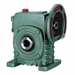
Technical Specifications — EO Series Double Worm Gear Reducer
Input Configuration
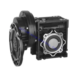
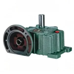
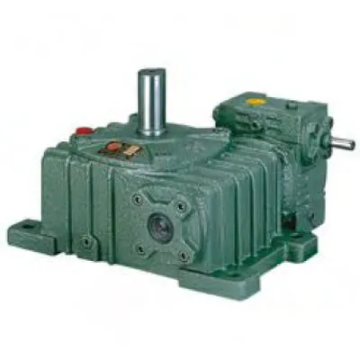
Through-shaft — motor couples to either input stub via jaw coupling. Unused stub sealed with blanking cap. Motor positioning fully flexible.
Output Configuration
Co-axial solid shaft exits both housing output faces on the same rotational axis. Connect to driven load from either output face — or both. Exact same speed and direction at both ends.
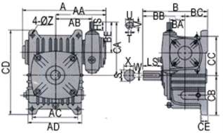
| Stage Pair | Overall Ratio | A (mm) | B (mm) | BB (mm) | CC Total (mm) | Input HS (mm) | Output LS (mm) | Output S (mm) | Key W (mm) |
|---|---|---|---|---|---|---|---|---|---|
| 50–80 | 200–900 | 289 | 210 | 140 | 320 | 30 | 65 | Ø32 | 10 |
| 60–100 | 200–900 | 352 | 245 | 155 | 375 | 40 | 75 | Ø38 | 10 |
| 70–120 | 200–900 | 417 | 285 | 185 | 450 | 40 | 85 | Ø45 | 12 |
| 80–135 | 200–900 | 462 | 320 | 210 | 495 | 50 | 95 | Ø55 | 15 |
| 100–155 | 200–900 | 542 | 392 | 252 | 590 | 50 | 110 | Ø60 | 15 |
| 120–175 | 200–900 | 585 | 412 | 262 | 640 | 65 | 110 | Ø65 | 18 |
Available Overall Ratios & Resulting Output Speeds (at 1,450 rpm input)
1/300 → 4.83 rpm
1/400 → 3.63 rpm
1/500 → 2.9 rpm
1/600 → 2.4 rpm
1/800 → 1.8 rpm
1/900 → 1.6 rpm
200:1–900:1
Through-Shaft Input — Either Side
Co-Axial Dual Solid Output
Double Self-Locking
6 Stage Pairs
EO vs EA — The Co-Axial Output Difference
| Feature | EA Series | EO Series |
|---|---|---|
| Input | Through-shaft (either side) | Through-shaft (either side) |
| Output exits | One housing face only | Both housing faces — co-axial |
| Output shaft connection | Single coupling / sprocket | Either or both output faces |
| Self-locking | Both stages, all ratios | Both stages, all ratios |
| Best for | Fixed output location | Output flexibility or dual load |
The EO’s practical value over the EA comes down to two specific situations: (1) the machine designer does not yet know which output face will be the active one at design time — the EO preserves this choice until the machine is built; (2) the application genuinely requires both output faces to be connected simultaneously, driving two loads co-axially at matched ultra-high reduction from a single worm gear set.
EO Key Advantages at Ultra-High Reduction Ratios
Output From Either Face — Design Flexibility
The co-axial output shaft exits both housing faces. The driven equipment can be connected from either side without changing the reducer specification. For OEM machine designs where the output connection point changes between configurations or customer variants, a single EO specification covers all options — no separate EA left-hand and right-hand variants needed.
Through-Shaft Input — Motor Either Side
The through-shaft input allows the motor coupling to be placed on either side of the first-stage housing. Combined with output from either face, the EO provides the maximum layout flexibility in the E-series range — four possible motor-plus-output-face combinations from a single housing design. For retrofit applications where machine structure constraints are unknown before delivery, this flexibility is commercially valuable.
Double Self-Locking — Holds Both Output Faces
Both worm stages self-lock simultaneously. Whether the driven load is connected to one output face or both, the self-locking mechanism holds the output shaft against back-drive from either direction on power-off. For gate valve actuators where the valve must hold position against flow-induced torque, this double locking acting on both output faces simultaneously provides redundant mechanical hold without any external brake.
Single Worm Wheel — Exact Co-Axial Speed Match
When both EO output faces are connected to separate driven loads, both rotate at exactly the same speed from the same worm wheel — no chain or belt synchronisation between them, no accumulated timing error. For co-axial twin drives requiring exact speed matching at ultra-low output speeds (2–7 rpm range), the EO provides factory-calibrated synchronisation that a chain-coupled pair of EA units cannot match over time.
Torque Distribution — Both Faces Combined Rating
When both output faces are loaded, the rated output torque is the combined total across both loads — the same principle as all co-axial dual-output units in this range. If each driven load requires T Nm, select the EO stage pair rated for 2T combined. Treating the rated torque as per-face capacity when both are loaded simultaneously is a specification error that overloads the second-stage worm wheel.
Single Oil Fill — Both Stages
The EO integrated housing shares oil across both worm stages. One fill point, one drain, one oil change per service interval — the same maintenance simplification as all E-series units versus two separate reducers in series. In remote Australian installations serviced infrequently, this single maintenance point per reducer is a genuine operational advantage.
Applications — Where the EO’s Dual-Face Output and Through-Shaft Input Both Matter
- 🌊 Gate Valve Actuators — Reversible Output, Either Face
EO 60-100 to 80-135 at 400:1–600:1 for gate valve and sluice actuators where the stem connection point may be on either side of the actuator housing depending on installation orientation. The EO’s output shaft accessible from both faces eliminates the need to specify left-hand or right-hand output variants for different installations. The through-shaft input allows the motor to clear structural members on either side. - ☀️ Solar Tracker Azimuth Drives — Co-Axial Twin-Panel Arrays
EO 50-80 to 70-120 at 500:1–800:1 for co-axial solar tracker arrays where two panel frames are driven simultaneously from a single central reducer, one frame connected to each output face of the EO. Both frames receive exactly matched rotation rate; the single reducer and motor is mounted centrally between the two frames. Self-locking holds both panel frames at the tracking angle throughout the night and during wind events without any external brake or latch. - 🧪 Fermentation and Biogas Stirrer Drives — Central Drive Pod
EO 60-100 at 300:1–500:1 for central stirrer drive pods where the impeller shaft enters the vessel from both the top and bottom. Both shaft ends rotate at exactly matched speed from a single worm wheel — critical in tall fermentation vessels where a top-only driven impeller creates dead zones at the bottom. The EO eliminates the separate bottom drive motor that would otherwise be required. - 🌾 Precision Seed Rate and Metering Drives
EO 50-80 at 200:1–400:1 for Australian precision agriculture metering systems where the output shaft must be accessible from both sides of the implement frame to drive bilateral metering rollers. The through-shaft input accommodates the PTO shaft adaptor on whichever side the tractor connection falls. For agricultural PTO shaft sizing, see PTO shaft specification resources. - 📡 Antenna and Telescope Positioning Systems
EO 70-120 to 100-155 at 600:1–900:1 for slow-rotation antenna azimuth or elevation drives in Australian remote telecommunications and radio astronomy installations. The output shaft exits both faces, allowing the driven load (azimuth ring gear or elevation arc) to be engaged from whichever face clears the structure. Self-locking holds the antenna at the programmed pointing angle without a holding brake, preserving pointing accuracy during power interruptions.
Drive Accessories and PTO Integration
Input Coupling — Either Stub, Not Both
The through-shaft input provides two motor stub ends. Connect the motor coupling to one stub only; seal the other with the blanking cap and inspect the blanking cap seal at every oil change. In dusty Australian environments, fit a secondary dust cap over the blanking cap — a failed blanking cap seal is the leading contamination ingress point for E-series through-shaft units.
PTO Adaptor + Slip Clutch
Yoke-end adaptor couples PTO shaft to either EO input stub. Friction slip clutch at 1.5× rated combined input torque is mandatory — when both output faces are loaded, one face jamming concentrates full PTO torque on the jammed load. Setting the clutch for single-face torque while dual-face is operational leaves the unit unprotected from full-torque jam events.
Oil — Both Stages, PAO for Continuous Duty
Two drain/fill points — one per stage. Both must be serviced independently at each oil change. PAO synthetic ISO VG 220 is recommended for EO units in continuous duty above 40°C ambient at ratios ≥ 400:1. Two-stage heat generation at high ratios combined with Australian summer ambient commonly pushes mineral-oil-filled E-series units to thermal limits that PAO oil avoids.
Output Shaft Guards — Both Active Faces
When only one EO output face is connected, the other output shaft stub must be guarded or shrouded — an exposed rotating shaft end is a safety non-compliance item under AS 4024. Fit a shaft end cap or stationary guard over the inactive output face on every EO installation where only one face is connected to the driven load.
Thermal Management
Two-stage efficiency loss generates more heat than single-stage. At ratios ≥ 500:1 and continuous duty, verify thermal rating at your ambient temperature. An external cooling fan raises the permissible continuous input power by 15–25% if the thermal calculation shows marginal headroom. Mounting the EO in a location with natural airflow around the housing is preferable to enclosing it in a sealed cavity without ventilation.
Coupling Selection — High Output Torque
At high ratios, output torque is very large relative to input power. At 600:1 with 0.37 kW input and η ≈ 0.50, combined output torque ≈ 730 Nm for EO 60-100. Select output couplings and sprockets for this torque level — not for the input power. This is the most common EO coupling under-specification error.
Maintenance Schedule — EO Series
| Interval | Task | EO-Specific Note |
|---|---|---|
| First 500 hr | Flush both stages; blanking cap seal check; output coupling torque | Inspect inactive output face for grease or seal weep — co-axial output seals on both faces run simultaneously even if only one is connected to a load |
| 2,500 hr | Oil change both stages; all seals; blanking cap lip seal | Replace blanking cap seal proactively in Australian agricultural/dusty environments — failed blanking seals are the primary contamination path for through-shaft E-series units |
| 5,000 hr | Both stage inspection; inter-stage bearing play; output shaft runout both faces | Check runout at both output faces — asymmetric wear between the two output end bearings indicates unequal loading history; investigate if differential is >0.03 mm TIR |
For EO stage pair selection, combined torque calculations when both output faces are loaded, thermal rating assessment, and dual-output mechanical guard design for Australian safety compliance, contact our engineering team at the worm gearbox technical portal. For project-specific procurement scheduling, reach us via the technical enquiry page. Further resources on agricultural and industrial gearbox integration in Australian conditions are available at gearboxagricultural.com.