Description
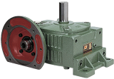
Technical Specifications — WDX & WDO Series Worm Gear Reducer
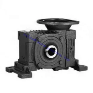
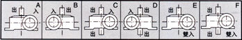
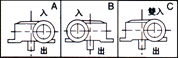
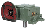
WDO — Co-Axial Dual Output
IEC B5 flange input + twin hollow bores on opposite housing faces. Both bores rotate at identical speed. Motor-direct input — no input coupling required. Best for parallel in-line synchronised shaft drives.
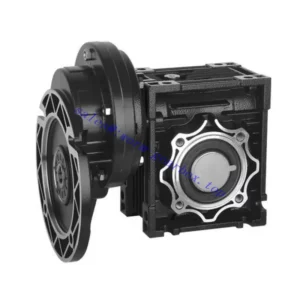
WDX — 90° Offset Dual Output
IEC B5 flange input + dual hollow bores at 90° offset. Internal bevel delivers the perpendicular output. Motor-direct input. Best for L-shaped twin-drive layouts without an external bevel stage.
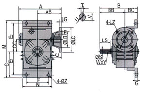
| Size | Power (kW) | Ratio | A (mm) | B (mm) | BC (mm) | E1 (mm) | Flange LA (mm) | Output S (mm) | Weight (kg) |
|---|---|---|---|---|---|---|---|---|---|
| 50 | 0.18 | 1/10–1/60 | 165 | 145 | 50 | 90 | 115 | Ø17 | 7 |
| 60 | 0.37 | 1/10–1/60 | 185 | 165 | 55 | 102 | 130 | Ø22 | 10 |
| 70 | 0.37/0.75 | 1/10–1/60 | 209 | 195 | 65 | 120 | 130 | Ø28 | 15 |
| 80 | 0.75/1.5 | 1/10–1/60 | 242 | 210 | 70 | 140 | 165 | Ø32 | 23 |
| 100 | 1.5 | 1/10–1/60 | 310 | 253 | 90 | 165 | 165 | Ø38 | 36 |
| 120 | 2.2/3.0 | 1/10–1/60 | 361 | 290 | 100 | 195 | 215 | Ø45 | 55 |
| 135 | 3.0/4.0 | 1/10–1/60 | 412 | 320 | 110 | 230 | 215 | Ø55 | 80 |
| 155 | 5.5 | 1/10–1/60 | 442 | 392 | 140 | 250 | 265 | Ø60 | 120 |
IEC B5 Input Flange — WDX/WDO
| Size | LZ (mm) | LB (mm) | Bolt | Input Q (mm) | Output Key W×Y |
|---|---|---|---|---|---|
| 50 | 140 | 95 | M8 | 25 | 5×3 |
| 60 | 160 | 110 | M8 | 35 | 7×4 |
| 70 | 160/200 | 110/130 | M8/M10 | 35/45 | 7×4 |
| 80 | 200 | 130 | M10 | 45/55 | 10×4.5 |
| 100 | 200 | 130 | M10 | 55 | 10×4.5 |
| 120 | 250 | 180 | M12 | 65 | 12×4.5 |
| 135 | 250 | 180 | M12 | 65 | 15×5 |
| 155 | 300 | 230 | M12 | 85 | 15×5 |
0.18–5.5 kW
IEC B5 Flange Input
Dual Hollow Bore Output
WDO: Co-Axial / WDX: 90°
Zero Couplings All Ends
Three Integration Wins in One Housing
The WDX/WDO takes the WX/WO twin-output concept and removes the last remaining coupling — the motor input. The WX/WO still required an input coupling between motor and through-shaft; the WDX/WDO replaces that with an IEC B5 flange, completing the zero-coupling drivetrain: motor flanges in, both driven shafts slide into bores. Three integration advantages are delivered simultaneously.
Factory-Exact Synchronous Twin Output
Both bores share one worm wheel — speed ratio between them is exactly 1:1, with zero phase error accumulation. Chain-synchronisation of separate reducers accumulates error from chain stretch and sprocket wear over time; the WDX/WDO is immune to both failure modes.
Motor-Direct Input — No Input Coupling
The IEC B5 flange eliminates the input coupling, coupling guard, and alignment step on the motor side. Motor shaft and worm shaft are co-axial within 0.05 mm TIR — machined from a single datum. No jaw coupling spider to replace, no angular misalignment generating cyclic input bearing load.
No Output Couplings — Both Driven Shafts Direct
Both output bores seat directly onto their driven shafts — two coupling bodies, two guards, and two alignment procedures removed simultaneously. In food processing environments, this eliminates two catch-point hazards and two moisture ingress gaps from the machine’s exposed surface.
Self-Locking at ≥ 30:1 — Both Bores Hold
At 30:1 and above, both output bores hold stationary on power-off simultaneously without any brake. In twin-auger systems loaded with full-column grain, both shafts are restrained against grain pressure at shutdown. The motor flange carries no coupling slip risk to the self-locking mechanism.
IEC Motor Interchangeability
Any IEC B5 motor of the correct frame drops onto the WDX/WDO flange without re-boring or motor base modification. Motor replacement from local Australian electrical stock on remote agricultural or mining sites avoids the extended downtime that motor-base-specific designs cause.
W Series Footprint — Legacy Machine Retrofit
External housing dimensions follow W series conventions. Foot pad bolt pattern, A, B, and H dimensions are unchanged from the W series baseline — existing W series machine mounts accommodate WDX/WDO without structural modification.
Critical: Combined Output Torque Rule
⚠️ Both bores share one worm wheel — the rated output torque is the combined total
If each driven shaft requires T (Nm), select a WDX/WDO rated for 2T combined output torque at the chosen ratio. Treating the rated torque as per-bore capacity results in 2× overload on the worm wheel and premature bronze wheel failure — the most common specification error on dual-output units across Australian service history.
- Calculate T1 and T2 (Nm) per driven load — apply individual shock service factors
- T_combined = T1 + T2 — this is the selection reference figure
- Select WDX/WDO where rated output torque ≥ T_combined at the selected ratio
- Verify thermal rating at T_combined / (ratio × η) input power in actual ambient temperature
Applications: When WDX/WDO Outperforms Separate Reducer Pairs
- 🌾 Twin-Auger Grain Handling Systems (WDO)
WDO size 100–120 at 30:1–40:1 drives twin matched grain augers from a single IEC motor. Both screws receive identical speed — eliminating grain bridging from differential auger velocity. Motor flanges directly, removing the input coupling gap that accumulates grain chaff and moisture in outdoor Australian grain handling installations. - 🚜 Agricultural Twin-Rotor Implements (WDX)
WDX size 80–100 drives a primary implement rotor and a perpendicular cross-conveyor or secondary rotor from one motor. The 90° bore geometry eliminates an external bevel stage. For tractor PTO input via a flange adaptor and slip clutch, refer to agricultural PTO shaft integration resources for sizing guidance. - 🍶 Fermentation and Mixing Tanks — Twin Paddle Drives (WDO)
WDO drives twin opposing paddles entering a fermentation or mixing vessel from both sides. Both paddles receive exactly matched speed and torque. Motor flanges directly to the reducer mounted on the vessel lid — no coupling body protrudes, and no coupling guard is needed between the motor and reducer. - 📦 OEM Packaging Infeed/Outfeed Pairs (WDO)
WDO size 60–80 at 20:1 drives matched infeed and outfeed conveyor belts from a single motor. Replaces two motor-reducer-VFD sets with one WDO and one VFD. Motor flanges directly — no motor base or input coupling body protrudes. Combined drive package is shorter axially than two separate drives, which matters in machine envelopes with fixed width constraints. - 🏭 Processing Line Corner Transfers (WDX)
WDX size 60–80 drives an in-line conveyor and a 90°-direction transfer simultaneously. No external bevel stage; no separate reducers and synchronisation chain. Motor-direct input eliminates the jaw coupling that would otherwise require periodic spider replacement in the high-vibration environment of a food processing line corner.
Input Options and Drive Accessories
IEC B5 Motor (Standard)
Standard 4-pole TEFC at 1,450 rpm. Confirm LZ/LB/Q/T×V against flange table before ordering. Motor shaft length must not exceed T×V bore depth — a bottomed-out shaft prevents correct flange seating. Input power must cover the combined torque of both driven loads at the selected ratio and efficiency.
PTO Shaft with Flange Adaptor
For tractor PTO input, a flange-end adaptor with friction slip clutch (set at 1.5× combined rated input torque) protects both the worm gear set and the twin-bore output during a jam on either driven shaft — when one bore jams, full motor torque concentrates on the stuck bore until the slip clutch trips.
Dual Shrink Discs (Shock Loads)
Both output bores require individual locking elements. For shock-load applications, specify shrink discs for both — uniform radial clamping across each bore depth prevents the progressive set screw loosening that repeated shock torques cause in either bore, which reinstates fretting risk.
Torque Arm — Combined Load Calculation
The torque arm carries the combined reaction torque of both output bores plus the motor + reducer gravitational weight moment. This is larger than WDX/WDO equivalent without flange motor — always recalculate when specifying the torque arm for flange-motor shaft-mount configurations.
Pressure-Equalising Breather
WDX/WDO has three shaft penetrations plus the flange bore — four total contamination and seal-weeping points. A breather vent prevents positive housing pressure from weeping oil at the bore seals during continuous-duty operation. The WDX additionally has internal bevel geometry that creates asymmetric oil splash patterns requiring breather fitting in any non-standard orientation.
Thermal Sensor (Sizes 100+)
Sizes 100 and above carry an NPT sensor port. In shaft-mounted configurations where the housing cannot be visually inspected during operation, a SCADA-connected PT100 provides the overtemperature protection that manual housing temperature checks cannot reliably deliver.
Maintenance Schedule — WDX/WDO Four-Point Protocol
| Interval | Task | WDX/WDO-Specific Note |
|---|---|---|
| First 500 hours | Oil flush; flange bolt check; both bore shrink discs | Inspect both bore-shaft contact zones for fretting — motor vibration transmitted through flange can accelerate early fretting at bore faces |
| Every 2,500 hours | Oil change; all seals; both shrink discs; motor flange bolts | Motor weight increases torque arm bush load — inspect bush radial clearance, replace if >0.8 mm |
| Every 5,000 hours | Remove both bores; full bore zone + motor bearing inspection | WDX: inspect 90° bore housing for any fretting at the bevel gear connection — asymmetric load can create differential wear rates between the two bore channels |
| If one bore jams | Full worm wheel and both bore inspection before return to service | Full motor torque concentrating at jammed bore can damage worm wheel even if motor trips promptly — do not assume no internal damage from visual inspection alone |
For WDX/WDO combined torque calculations, IEC motor frame verification, shrink disc selection, and torque arm combined load design for Australian plant, the engineering team at our worm gearbox technical portal provides application-specific support. For agricultural dual-implement drive integration, contact us via the technical enquiry page. Further resources on synchronised agricultural drive systems are available at gearboxagricultural.com.