Description
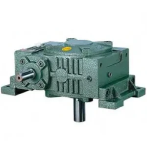
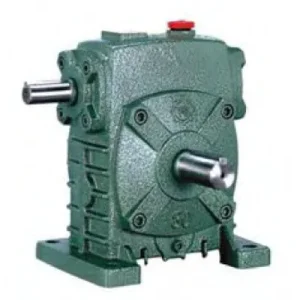
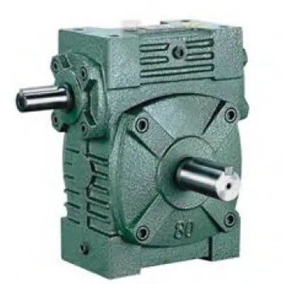
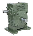
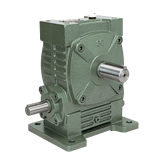
The WA & WS Series Worm Gear Reducer — designated WA (hollow bore output, WPA-class bore depth) and WS (hollow bore output, WPS-class bore depth) — are the hollow-bore output members of the W family, maintaining the W series’ through-shaft input geometry while replacing the solid output stub with a keyed bore that seats directly onto the driven shaft. The WS delivers the longer bore depth, deeper output bearing span, and greater permissible overhung load of the W series’ deeper output section, while the WA suits lighter-duty shaft-mount applications where the W series dimensional footprint is required but heavy shock loads are not present. Together, this pair covers the complete range from small indexing drives at size 40 up to heavy-duty conveyor and material handling at size 200 — all within the W series dimensional convention that Australian legacy plant was originally designed around. The through-shaft input means either side of the reducer accepts the motor, retaining the layout flexibility that characterises the W series across its full hollow-bore range.
Technical Specifications — WA & WS Series Worm Gear Reducer
WS Series — Output Configuration
WPS-class bore depth (HL). Longer key engagement, deeper bearing span, higher OHL. Through-shaft input both sides. Preferred for chain/belt driven loads and shock applications within W series machines.
WA Series — Output Configuration
WPA-class bore depth (HL). Shorter bore engagement, lighter bearing arrangement. Through-shaft input both sides. Suitable for smooth continuous loads in legacy W series equipment at sizes 40–200.
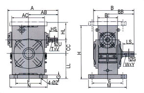
| Size | Ratio | A (mm) | B (mm) | H (mm) | HL-WS (mm) | HL-WA (mm) | Output Bore S (mm) | Weight (kg) |
|---|---|---|---|---|---|---|---|---|
| 40 | 1/10–1/60 | 148 | 122 | 135 | 60 | 45 | 14 | 4 |
| 50 | 1/10–1/60 | 175 | 145 | 165 | 80 | 50 | 17 | 7 |
| 60 | 1/10–1/60 | 195 | 165 | 195 | 93 | 60 | 22 | 11 |
| 70 | 1/10–1/60 | 234 | 195 | 233 | 108 | 73 | 28 | 15 |
| 80 | 1/10–1/60 | 264 | 210 | 268 | 123 | 83 | 32 | 23 |
| 100 | 1/10–1/60 | 322 | 245 | 330 | 150 | 100 | 38 | 38 |
| 120 | 1/10–1/60 | 385 | 285 | 395 | 180 | 120 | 45 | 65 |
| 135 | 1/10–1/60 | 435 | 320 | 455 | 215 | 135 | 55 | 84 |
| 155 | 1/10–1/60 | 494 | 387 | 493 | 235 | 135 | 60 | 114 |
| 175 | 1/10–1/60 | 548 | 407 | 558 | 260 | 160 | 65 | 150 |
| 200 | 1/10–1/60 | 688 | 480 | 620 | 290 | 175 | 70 | 218 |
Ratio 10:1–60:1
Through-Shaft Input
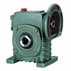
Hollow Bore Output
WS: Deep Bore (Shock-Rated)
WA: Standard Bore

Through-Shaft Input and Hollow Bore Output — Two Layout Freedoms in One Unit
The WA/WS series combines two configuration features that individually characterise different WP series members: the through-shaft input (W series characteristic) and the hollow bore output (WPKA/WPKS characteristic). No single WP series unit offers both simultaneously. The WA/WS is the correct specification when both are needed — when the application requires shaft-mount output onto a driven shaft and the motor position must be flexible between left and right of the reducer without changing the output direction.
Motor on Either Side — Zero Layout Constraint
Through-shaft input means the motor couples to either the left or right input stub without changing the output direction. In machines where operator access, safety guarding, or structural interference forces the motor to one side, the WA/WS accommodates this without a new reducer specification or output coupling reversal.
No Output Coupling — Shaft-Mount Direct
The hollow bore output eliminates the output coupling, coupling guard, and output shaft alignment procedure. The driven shaft is the mounting reference — the reducer seats directly onto it. In conveyor head shaft retrofits within existing W series machine lines, this eliminates the output coupling body without changing the input side arrangement.
W Series Dimensional Convention — Legacy Compatible
The WA/WS follows W series external dimensions — A, B, H, and foot pad configuration all match the W series convention. When replacing a W series solid-output unit with a WA/WS hollow-bore unit in legacy equipment, the mounting baseplate is unchanged. Only the output coupling is removed and the bore slides onto the shaft.
WS: Shock-Rated Deep Bore — WPKS-Class
The WS bore depth (HL-WS column) matches the WPS-class hollow bore. At size 100, WS HL = 150 mm versus 100 mm in the WA. This additional bore engagement reduces key face pressure under shock loads and prevents the fretting that destroys shallow-bore reducers in conveyor jam events and agricultural stone-strike scenarios.
Self-Locking at ≥ 30:1
Effective static self-locking at ratios 30:1 and above — position is held on power-off without a motor brake. The hollow bore connection transmits this holding torque directly into the driven shaft through the key engagement area. WS bore depth provides greater key engagement area for this static holding duty, reducing bore fretting under sustained static loads.
Sizes 40–200 — Full W Range Coverage
The WA/WS range extends to size 200 — covering the largest W series applications at 200 kg unit weight and 70 mm output bore diameter. No hollow-bore WP series equivalent reaches this frame size, making the WA/WS the only hollow-bore specification option for the largest Australian conveyor and material handling applications within the W series dimensional family.
WA vs WS: Selecting the Right Bore Depth for Your Driven Shaft
| Selection Criterion | WS (Deep Bore) | WA (Standard Bore) |
|---|---|---|
| Bore depth (HL at size 100) | 150 mm | 100 mm |
| Shock load rating | High (SF up to 2.5) | Moderate (SF up to 1.5) |
| Axial shaft load (screw conveyor) | Acceptable | Not recommended |
| Locking element recommendation | Shrink disc (shock) or set screw (smooth) | Set screw (smooth loads) |
| Applications | Conveyors, augers, screw drives, hoists | Mixers, turntables, packaging, positioning |
| Cost vs WA | Marginally higher | More economical |
Construction Details: How Through-Shaft Input and Hollow Bore Output Coexist
Housing with Four Machined Bore Locations
The WA/WS housing carries four precision bore locations machined from a common datum: two input shaft bores (one each side of the housing on the worm shaft axis) and one output bore (passing through the worm wheel hub). The output bore is the structurally demanding feature — it must maintain H7 dimensional integrity within the worm wheel hub while the hub carries the full output torque. The WS housing provides additional hub wall thickness versus the WA at each size, consistent with the deeper bore requirement. Both series retain the W series foot-mount pad configuration and housing proportions, confirming their dimensional compatibility with existing W series machine mounts.
Input Shaft Through-Configuration — Sealing the Unused Stub
The worm shaft passes completely through the housing and is supported by bearings at both input faces — identical to the W series solid-output unit. The unused input stub is sealed with a blanking cap and lip seal. This seal is a critical maintenance item: contamination through a failed blanking cap is the most common cause of oil contamination and premature worm wheel wear in both the W and WA/WS series in Australian agricultural and dusty industrial environments. Inspect the blanking cap seal at every scheduled oil change and replace when the lip shows wear or hardening.
Output Bore Key and Locking Element
The WA/WS output bore is machined with a DIN 6885 Form A parallel keyway at the W×Y dimensions from the specification table. A parallel key seated in both bore and shaft keyways transmits the output torque. For WA units on smooth continuous loads, a set screw provides adequate retention. For WS units on shock or cyclic loads, a shrink disc is the recommended locking element — uniform radial clamping over the full WS bore depth prevents progressive set screw loosening under repeated shock torque cycles, which is the dominant bore connection failure mode in WA units on incorrectly-rated shock applications.
Application Environments — Where WA/WS Dual Flexibility Matters
- 🔄 Legacy W Series Machine Upgrades — Shaft Mount Conversion
When an existing W series machine is upgraded from a solid-shaft output to direct shaft-mount output (eliminating the output coupling as part of a maintenance simplification programme), replacing the solid-output W series reducer with a WA or WS keeps the existing baseplate, input coupling, and motor position unchanged. Only the output connection changes. - 📦 Packaging Machine Drives with Motor Position Constraint
Packaging machines in Australian food production frequently have the motor position constrained by safety guarding, conveyor structure, or operator access panels. The WA/WS through-shaft input accommodates motor positions on either side without changing the reducer mounting position or output shaft rotation direction — a layout problem that requires a more complex solution with WP series hollow-bore units. - 🌾 Agricultural Auger and Metering Drives
WS size 80–120 units bore-mount directly on grain auger shafts in Australian bulk handling. The through-shaft input allows the drive motor to be positioned to avoid collision with the grain hopper structure — a common layout challenge in auger head shaft arrangements. The WS bore depth handles routine stone strike events without keyway fatigue. - 🔩 Textile and Printing Machine Through-Drive Lines
Multi-section production lines where a single drive shaft distributes power to several machines via branching W series reducers use WA/WS units at the branch points that require shaft-mount output onto process shafts. The through-shaft input allows the main drive shaft to pass through the reducer and continue to the next branch point. - 🏗️ Heavy Conveyor Head Shaft Drives (WS Size 155–200)
At size 200, the WS bore (Ø70 mm, HL = 290 mm) handles the largest conveyor head shaft diameters found in Australian mining bulk handling. No hollow-bore WP series unit reaches this frame, making the WS200 the only available specification for bore-mount applications at this scale within the W series family. - 🚿 Irrigation and Water Infrastructure Drives
Gate actuators and mixer drives in Australian irrigation infrastructure use WA size 60–100 for their sealed housing, self-locking at high ratios, and the ability to position the motor on either side of the reducer to clear the headstock structural members — a layout constraint that the W series’ through-shaft input resolves more cleanly than a WP series hollow-bore unit would.
PTO Integration and WA/WS Drive Accessory Components
The WA/WS solid input stub configuration accepts any standard coupling. For agricultural tractor-driven applications, a PTO shaft assembly connects to whichever input stub is on the convenient side — the other stub remains capped. Key accessory considerations:
PTO Shaft and Yoke Coupling
A standard PTO shaft with implement-end yoke coupling connects the tractor 540/1000 rpm output to either WA/WS input stub. Couple to the most geometrically convenient side; cap and seal the other. Fit a friction slip clutch between PTO shaft and reducer input for agricultural shock-load protection.
Torque Arm (Shaft-Mount Configuration)
A torque arm anchors the WA/WS housing against reaction torque when bore-mounted. Because the W series housing is taller than the WP equivalent, the torque arm attachment point is at a higher elevation — confirm the arm length and rubber bush rating accommodate the combined motor + reducer weight moment at this taller mounting height.
Shrink Disc (WS Shock Applications)
For WS units on shock-loaded applications, a shrink disc replaces the set screw. For WA units on smooth continuous loads, a correctly torqued set screw over the bore key is adequate — but consider upgrading to a shrink disc if the application subsequently requires higher shock tolerance without changing the reducer.
Unused Input Stub Blanking Cap
The unused input stub must remain sealed with the blanking cap and lip seal at all times. In dusty or wet Australian environments, fit a secondary labyrinth dust cap over the standard blanking cap as an additional contamination barrier. Neglecting this seal is the leading cause of premature worm wheel wear in W series units across Australian field service history.
Oil Fill and Breather
ISO VG 220 mineral gear oil standard fill. For shaft-mount orientations, confirm the correct fill level for the installed orientation. A pressure-equalising breather at the filler port is recommended for continuous duty operations to prevent positive internal pressure from weeping oil past the shaft seals.
Thermal Monitoring (Large Sizes)
WS size 120 and above units used in continuous duty at high ratios in warm Australian ambient conditions benefit from a thermal sensor at the NPT port, particularly when the reducer is bore-mounted on a shaft where housing temperature cannot be directly observed during operation.
Maintenance Schedule — WA/WS Hollow Bore Through-Shaft Configuration

| Interval | Task | WA/WS-Specific Note |
|---|---|---|
| First 500 hours | Oil drain and refill; shrink disc re-torque if fitted | Check both input shaft seals AND the blanking cap seal — four seal locations total in WA/WS |
| Every 2,500 hours | Full oil change; inspect all four seals; check blanking cap | Replace blanking cap lip seal if any hardening or wear visible — do not wait for visible oil seepage from unused stub |
| Every 5,000 hours | Remove from shaft; bore-shaft zone inspection; bearing clearance | WS: check for fretting powder at bore end faces; WA: check set screw torque and bore surface condition |
| Input direction change | 180° shaft reversal procedure (same as W series) | Drain and replace oil after reversal; slowly mesh shafts by hand — never force-insert |
| After shock event (WS) | Inspect bore zone and shrink disc torque | Even the WS deep bore can initiate fretting after a severe single shock event — inspect before assuming no damage |
For WA/WS series dimensional cross-referencing with legacy W series equipment, bore size confirmation, torque arm design assistance, and application-specific selection support for Australian plant, the engineering team at our worm gearbox technical portal provides detailed support. Contact us via the technical enquiry page with your driven shaft diameter, load torque, shock factor, and ambient temperature for a confirmed selection recommendation.