Description
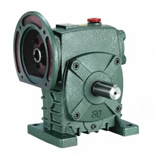
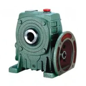
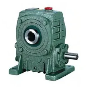
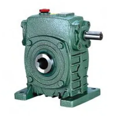
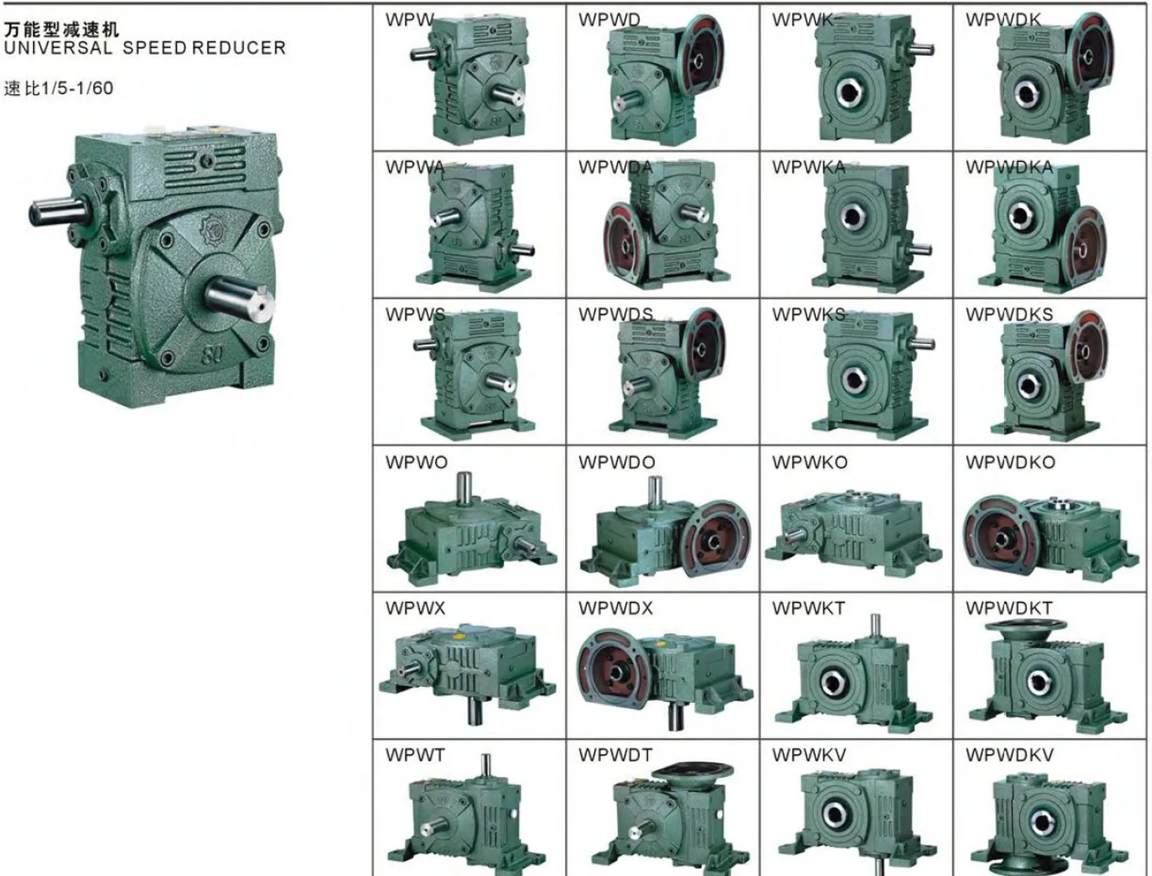
The WP Series Single Standard Worm Gear Reducer — WPKS is the hollow-bore output counterpart to the WPS, carrying the same enlarged output shaft geometry, extended bore length, and WPS-class bearing arrangement, while replacing the solid output stub with a through-bore that mounts directly onto the driven shaft. For Australian engineers specifying a worm gear reducer for chain-loaded conveyors, heavy screw drives, or agricultural implement shafts, the WPKS offers something the WPKA cannot: a longer bore depth, a larger bore diameter at each frame size, and tapered roller output bearings at sizes 80 and above — all of which translate directly to a substantially higher permissible output torque at the bore connection and a greater resistance to shaft fretting under shock loads. Covering sizes 50 through 200 with 10:1 to 60:1 ratios and input powers rated to match, the WPKS is the hollow-bore specification for demanding applications where the WPKA would be undersized.
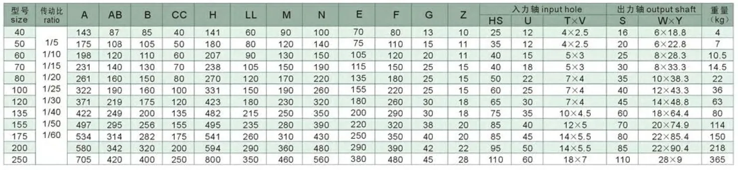
Technical Specifications — WP Series (WPKS) Hollow Bore Worm Gearbox
| Size | Ratio | A (mm) | AB (mm) | B (mm) | H (mm) | HL (mm) | Output Bore S (mm) | Weight (kg) |
|---|---|---|---|---|---|---|---|---|
| 50 | 1/10–1/60 | 175 | 105 | 107 | 180 | 130 | Ø20 | 7 |
| 60 | 1/10–1/60 | 195 | 120 | 117 | 205 | 150 | Ø25 | 10.5 |
| 70 | 1/10–1/60 | 234 | 140 | 131 | 235 | 175 | Ø30 | 14.5 |
| 80 | 1/10–1/60 | 264 | 160 | 144 | 265 | 200 | Ø35 | 22 |
| 100 | 1/10–1/60 | 322 | 190 | 175 | 327 | 250 | Ø40 | 36 |
| 120 | 1/10–1/60 | 385 | 230 | 200 | 388 | 300 | Ø45 | 63 |
| 135 | 1/10–1/60 | 435 | 260 | 212 | 445 | 350 | Ø60 | 80 |
| 155 | 1/10–1/60 | 507 | 302 | 312 | 483 | 390 | Ø70 | 114 |
| 175 | 1/10–1/60 | 550 | 325 | 334 | 540 | 435 | Ø80 | 150 |
| 200 | 1/10–1/60 | 670 | 350 | 346 | 610 | 490 | Ø85 | 218 |
Input Shaft & Output Key Dimensions — WPKS Series
| Size | Input HS (mm) | Input U (mm) | Input Key T×V (mm) | Output Key W×Y (mm) |
|---|---|---|---|---|
| 50 | 30 | 12 | 4×2.5 | 6×22.8 |
| 60 | 40 | 15 | 5×3 | 8×28.3 |
| 70 | 40 | 18 | 5×3 | 8×33.3 |
| 80 | 50 | 22 | 7×4 | 10×38.3 |
| 100 | 50 | 25 | 7×4 | 12×43.3 |
| 120 | 65 | 30 | 7×4 | 14×48.8 |
| 135 | 75 | 35 | 10×4.5 | 18×64.4 |
| 155 | 85 | 40 | 10×4.5 | 20×74.9 |
| 175 | 85 | 45 | 12×4.5 | 22×85.4 |
| 200 | 95 | 50 | 12×4.5 | 22×89.4 |
Ratio 10:1 – 60:1
Hollow Bore Ø20–85mm
WPS-Grade Bore Depth
Tapered Roller (Size 80+)
Cast Iron Housing
WPKS vs WPKA: Why the Larger Bore Depth Changes the Application Envelope
The WPKS and WPKA carry identical bore diameters at each size number — the difference is in the bore depth (HL dimension) and the output bearing arrangement. At WPKS size 100, the HL dimension is 250 mm versus 100 mm on the WPKA. This deeper bore engagement reduces the key surface pressure under a given output torque by a factor of 2.5, directly extending the service life of the keyway contact surfaces under shock loading. Combined with the tapered roller output bearings at sizes 80 and above, the WPKS handles applications that the WPKA cannot sustain reliably.
Deep Bore — Higher Key Engagement
The WPS-class HL dimension at each size gives the WPKS bore more than twice the key engagement length of the WPKA. This halves the key face pressure at a given torque — critical for shock-loaded applications such as grain augers striking stones, chain conveyors with stuck loads, or any cyclic reversing drive where fretting at the key face initiates fatigue cracking.
Tapered Roller Bearings at Sizes 80+
The WPKA uses deep-groove ball bearings throughout. The WPKS installs tapered roller bearings on the output side at sizes 80 and above — these carry a substantially higher radial load and also absorb moderate axial shaft loads from helical-cut driven elements or axially loaded screw conveyors, failure modes that ball bearings handle poorly under sustained load.
Cast Iron Structural Rigidity
The WP series uses grade 250 grey cast iron housing throughout. Cast iron absorbs vibration more effectively than aluminium (common in compact NMRV units) and is dimensionally stable under the temperature cycling of continuous-duty Australian plant environments. Bore diameter remains within H7 tolerance across the full –40°C to +40°C operating temperature range specified for this series.
Multiple Input and Output Configurations
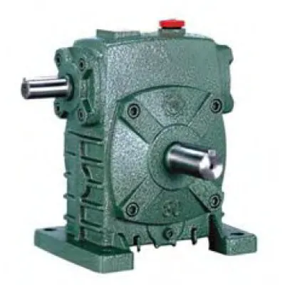
The WPKS accepts solid shaft input, hollow bore input (for PTO shaft connection), or flange input — and delivers hollow bore output. This flexibility means the same reducer series can be specified across electric motor drives, PTO shaft agricultural drives, and hydraulic motor interfaces without changing the output bore configuration.
Self-Locking Under Static Loads ≥ 30:1
At ratios of 30:1 and above, both the WPKS and WPKA exhibit self-locking under static conditions. The WPKS transmits this holding torque through the deeper bore engagement, reducing the risk of driven shaft fretting at the bore contact zone during static holding periods under sustained axial or radial loads that can occur in vertical shaft applications.
Operating Range –40°C to +40°C
The WPKS working environment temperature spans –40°C to +40°C. For Australian applications: in cold-room conveyors and refrigerated processing plants operating below 0°C, ISO VG 68 or synthetic VG 100 oil must be substituted and the unit pre-warmed to above 0°C before initial startup. At ambient above 40°C (enclosed summer sheds), active cooling or synthetic oil is required.
Engineering Construction: The WPS Housing Carries the Hollow Bore Differently
Bore-to-Hub Wall Thickness and Structural Analysis
The WPKS bore passes through the worm wheel hub — a structural feature that must maintain adequate wall thickness between the bore surface and the outermost diameter of the worm wheel gear teeth. The WPS housing geometry provides more wall thickness at each size than the WPA/WPKA equivalent, which is the structural reason the WPKS can sustain a larger bore depth (HL dimension) without compromising hub rigidity. At size 100, the WPKS HL of 250 mm maintains a minimum hub wall thickness of 22 mm — well above the 12 mm minimum threshold for DIN 743 shaft-hub connection calculations at the rated output torque.
Worm Gear Set: American Technology Benchmark
The WPKS worm gear set is designed to the WP series specification, which was originally developed following American worm gear technology practices — specifically the AGMA 6034 standard for cylindrical worm gearing. This gives the WPKS several geometry parameters that differ from DIN-based designs: a pressure angle of 20° (versus 14.5° in some older DIN designs), which increases contact stress capacity and reduces undercutting risk at higher ratios. The worm shaft induction hardening depth is specified to exceed 1.5 mm on the flank — ensuring full hardened layer retention through the rated tool life of the bronze wheel before the worm thread root reaches the soft core material.
Lubrication and Working Conditions
The WPKS specifies that the worm input speed cannot exceed 1,500 rpm — a limit set by the oil splash lubrication effectiveness at the worm-wheel mesh. Above 1,500 rpm, the oil is centrifuged away from the mesh before the worm thread can carry it into the contact zone, causing starvation lubrication and accelerated bronze wheel wear. Standard 4-pole motors at 1,450 rpm are at the permissible limit; 2-pole motors at 2,900 rpm are incompatible with the WPKS without an intermediate speed reduction stage. For VFD-operated WPKS units, the 1,500 rpm input speed limit is an absolute constraint that overrides the VFD’s ability to operate above nominal frequency — do not programme the VFD above 50 Hz (for 4-pole motors) when driving a WPKS.
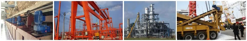
High-Demand Applications Where the WPKS Outperforms the WPKA
The WPKS targets applications where the driven shaft diameter, shock load severity, or sustained output torque level falls outside the reliable capability of the WPKA at the same size number. Each of the following represents a specific engineering fit:
- 🌾 Heavy-Duty Grain and Seed Auger Head Drives
Auger shafts in Australian bulk grain handling commonly reach 60–70 mm diameter at size 135–155 — shafts that the WPKA bore can accept but which require the WPKS bore depth for adequate key engagement torque capacity under the shock loads of grain stone strikes. A WPKS135 at 30:1 on a 60 mm auger shaft handles the combined continuous torque plus 2× peak shock factor without keyway fretting that would require shaft replacement within one season. - 🏗️ Screw Conveyor Drives with Axial Shaft Loading
Screw conveyors transporting heavy or sticky materials (cement, mineral sands, tailings slurry) generate significant axial thrust at the head shaft from the helical screw geometry. The WPKS tapered roller bearings at sizes 80 and above can sustain this axial thrust load; the WPKA’s ball bearings at the same sizes cannot — they are designed for radial load and only moderate axial loads within the C0/Fr ratio limits. Specifying a WPKA for a screw conveyor with sustained axial load is the most common cause of premature output bearing failure in this application. - 🏭 Plastics and Rubber Extruder Screw Drives
Extruder screws in Australian plastics and rubber processing machinery carry both high torque and axial thrust from the material pressure in the screw channel. A WPKS at 20:1–40:1 mounted on the extruder screw shaft handles both load components simultaneously. The deeper bore engagement prevents keyway fatigue under the high-cycle torque reversals that occur on extruder screws at purge and startup — a failure mode that requires complete bore replacement when it occurs in an inadequately specified WPKA. - 🔩 Mining Conveyor Belt Head Drum Drives
Underground and open-cut mining conveyors in Australia run continuously under heavy loads with frequent emergency stops and belt slippage incidents that impose shock torques of 3–5× rated continuous torque on the head shaft drive. The WPKS handles these shock events through the deeper bore engagement and the tapered roller bearing arrangement — a combination that keeps the bore-shaft connection intact through start/stop cycles that would progressively loosen an WPKA’s set screw connection within weeks. - 🚜 PTO-Driven Agricultural Implement Shafts
Heavy-duty agricultural implements — rotary tillers, mulchers, flail mowers — drive through large-diameter implement shafts at high torque. A WPKS bore-mounted on the implement main shaft accepts the tractor PTO input through the solid input stub, reducing the implement’s output speed to 50–150 rpm while maintaining the self-locking characteristic at the shaft bore under static hold conditions when the tractor is stationary and the implement is loaded. For PTO shaft integration details and slip clutch sizing for this application, PTO shaft assembly selection guides are available from our technical team. - 🏗️ Winch and Hoist Drum Drives (AS 1418 Compliance)
Australian Standard AS 1418 requires that manually suspended load hoist drives demonstrate a minimum static load-holding factor — the worm self-locking at 30:1 and above provides this function in the WPKS. The deeper bore engagement distributes the static holding torque over a greater key length than the WPKA, reducing the stress concentration that causes keyway cracking in frequently loaded-and-released hoist applications.
PTO Integration, Input Variants, and Drive Accessories for the WPKS
The WPKS accepts three different input configurations — making it one of the most flexible members of the WP family for integration into existing drivetrains. Each input variant pairs with specific accessory requirements:
PTO Shaft — Hollow Input Bore Variant
The WPKS hollow input bore variant accepts PTO shaft spline direct through the input end, eliminating the standard solid input stub. This allows the agricultural PTO shaft to connect without a separate coupling — the spline engages the input bore directly, reducing the implement drive length by the coupling body dimension.
Solid Shaft Input + Motor and Coupling
Standard solid input stub accepts any motor through a jaw coupling and motor base. For WPKS units with WPS-class output bore, the solid input is the most flexible option — allowing motor position adjustment without changing the bore-mount position on the driven shaft.
Flange Input Variant (WPKS + Motor Flange)
A flange input option combines the hollow bore output of the WPKS with the IEC B5 motor flange input of the WPDS — effectively the WPKDS configuration for applications requiring both motor-direct input and hollow-bore shaft-mount output. This is available as a custom variant with 4–6 week lead time.
Torque Arm Assembly
In shaft-mount configuration, the torque arm anchors the WPKS housing to a fixed structural point. For WPKS units on heavy conveyor head shafts where shock loads are expected, a heavy-duty torque arm with dual rubber-bushed end connections provides better shock absorption than a single-bushed design, reducing fatigue at the arm anchor point.
Shrink Disc (Strongly Recommended)
For WPKS applications with shock loading, reversing torque, or sustained axial shaft forces, a shrink disc at the output bore replaces the set screw as the mandatory locking element. The clamping force across the full bore length prevents fretting — the dominant failure mechanism in heavy-duty hollow-bore reducer applications in Australian mining and bulk handling.
Synthetic PAO Gear Oil (High Duty)
For WPKS units operating at high ratios (40:1+) in continuous duty at above 30°C ambient, ISO VG 220 PAO synthetic gear oil extends the thermal rating by 10–15% compared to mineral oil and doubles the service interval to 5,000 hours — a meaningful maintenance saving across large WPKS fleets in Australian mining and processing operations.
Operating Conditions, Limits, and Precautions for WPKS Service Life
Three Critical Operating Precautions
The WPKS product documentation specifies three absolute operating constraints that maintenance and commissioning engineers must observe — violations of any one of these is the primary cause of premature failure:
LIMIT 1 Input Speed ≤ 1,500 rpm
The worm input speed is capped at 1,500 r/min. Standard 4-pole motors at 1,450 rpm comply; 2-pole motors do not. VFD setpoints above 50 Hz on 4-pole motors must be blocked at the drive parameter level.
LIMIT 2 Ambient –40°C to +40°C
Below 0°C: pre-warm to above 0°C before startup; substitute lower-viscosity oil (ISO VG 68 or synthetic VG 100). Above 40°C: active cooling required (fin kit, fan, or synthetic PAO oil as minimum intervention).
LIMIT 3 Worm Shaft Is the Input — Always
The worm wheel shaft (output bore) must never be used as the drive input. Back-driving through the bore at ratios where the unit is self-locking destroys the worm mesh — the worm wheel thread cannot drive the worm thread without catastrophic tooth face damage.
Input Direction Reversal Procedure
If the application requires reversing the input shaft rotation direction after installation — for example, re-orienting a conveyor drive — the WPKS documentation specifies a defined procedure: remove the lower end cover of the input shaft, extract the worm shaft, rotate 180°, and reinsert. This reverses the input rotation direction while maintaining the same output rotation direction. The procedure requires no special tools but must be performed with the unit stationary and de-energised. Critically, the two shafts must be engaged by slowly rotating until teeth mesh without forcing — forced engagement damages worm tooth flanks and generates metal debris in the oil bath that accelerates bronze wheel wear.
Self-Locking Behaviour: What It Means in Practice for Australian Applications
The self-locking characteristic of the WPKS is one of the most commercially cited features of the WP series — and also one of the most misunderstood. A clear understanding of when it applies and when it does not prevents both over-reliance and missed specifications:
| Ratio | Static Self-Locking | Dynamic Back-Driving | Practical Note for AS Applications |
|---|---|---|---|
| 10:1 – 15:1 | Not self-locking | Back-drivable | Motor brake required for gravity loads; do not use for load-holding without auxiliary brake |
| 20:1 | Marginal | Borderline | Self-locking only at low friction — vibration or shock can cause creep; verify with application data |
| 30:1 – 60:1 | ✓ Self-locking | Not back-drivable | Position-holding on power-off; suitable for load-holding in compliance with AS 1418 secondary brake requirement (with engineering assessment) |
The self-locking behaviour holds under static conditions at rated load. It should not be relied upon as the sole means of load restraint for suspended personnel loads under AS 1418.3 — Australian Standards require a dedicated mechanical brake in those applications regardless of gearbox self-locking. For gravity-loaded material handling (grain bins, aggregate hoppers, chemical tanks) the worm self-locking is an appropriate and widely accepted secondary load-holding device. For broader worm gearbox technical guidance on self-locking applications across Australian industry, the engineering team at our technical portal can provide application-specific assessment documents for inclusion in machinery safety files.
Maintenance Programme for WPKS in Heavy-Duty Australian Service
| Interval / Trigger | Task | WPKS-Specific Note |
|---|---|---|
| First 500 hours | Oil drain and refill; shrink disc or set screw re-torque | Inspect bore-shaft contact zone for early fretting (rust-brown powder) — indicates inadequate locking force |
| Every 2,500 hours | Full oil change; all seals and torque arm bush inspection | Re-torque shrink disc bolts in cross pattern; check torque arm rubber bush for cracking or collapse |
| Every 5,000 hours | Remove bore from shaft; inspect bore and shaft contact | Check tapered roller bearing radial play (sizes 80+): >0.08 mm warrants replacement; shock-loaded applications may need earlier inspection |
| After any jam event | Full inspection: worm wheel flank, bore contact, bearings | Even a single jam event in a 3–5× shock load application can initiate keyway fatigue crack — inspect before returning to service |
| At worm wheel replacement | Measure bore diameter and check for out-of-round | Bore distortion from prolonged fretting compromises the new wheel’s concentricity — if bore is out of round >0.05 mm, reline or replace the housing |
For bore size confirmation, shrink disc selection, input configuration options, and application torque calculations for the WPKS across Australian mining, agricultural, and processing industries, contact our engineering team via the technical enquiry page. Our team can also confirm stock availability and lead time for non-standard configurations. Further resources on hollow-bore worm gearbox integration into agricultural power transmission systems are available at gearboxagricultural.com.