Description
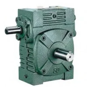
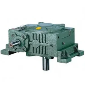
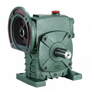
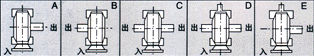
The WDA & WDS Series Worm Gear Reducer — designated FCWDA and FCWDS respectively — complete the W family’s motor-flange variants by combining the IEC B5 input flange of the FCWD with the hollow bore output of the WA and WS series. The FCWDA provides IEC flange input and WA-class hollow bore output — suited for smooth continuous shaft-mount applications where motor-direct convenience is required. The FCWDS upgrades to the WS-class deeper bore depth — delivering greater key engagement, higher shock torque tolerance, and superior fretting resistance for chain-loaded conveyors, auger stone-strike scenarios, and screw conveyor axial thrust duty where the motor must flange-mount and the output must shaft-mount simultaneously. Together, they represent the maximum integration achievable within the W family: zero couplings at either end, W series dimensional convention, through-shaft input flexibility, and the choice of bore depth matched to the application’s shock load reality. Sizes 50 through 155, 0.18 kW to 5.5 kW, ratios 10:1 to 60:1.
Technical Specifications — WDA & WDS Series (FCWDA / FCWDS)
FCWDA — WA-Class Bore Depth
IEC B5 flange input + WA-class hollow bore output (shorter HL). Motor-direct + shaft-mount for smooth continuous loads, turntables, mixers, and positioning drives where shock loads are not present.
FCWDS — WS-Class Bore Depth
IEC B5 flange input + WS-class hollow bore output (deeper HL). Motor-direct + shaft-mount for shock loads, conveyors, auger stone strikes, and screw conveyor axial thrust where the FCWDA bore depth is insufficient.
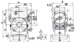
| Size | Power (kW) | Ratio | A (mm) | B (mm) | H (mm) | HL-WDS (mm) | HL-WDA (mm) | Flange LA (mm) | Bore S (mm) | Weight (kg) |
|---|---|---|---|---|---|---|---|---|---|---|
| 50 | 0.18 | 1/10–1/60 | 165 | 175 | 165 | 80 | 50 | 115 | 17 | 7 |
| 60 | 0.37 | 1/10–1/60 | 185 | 190 | 195 | 93 | 60 | 130 | 22 | 11 |
| 70 | 0.37/0.75 | 1/10–1/60 | 209 | 210 | 233 | 108 | 73 | 130 | 28 | 15 |
| 80 | 0.75/1.5 | 1/10–1/60 | 242 | 240 | 268 | 123 | 83 | 165 | 32 | 23 |
| 100 | 1.5 | 1/10–1/60 | 310 | 263 | 330 | 150 | 100 | 165 | 38 | 38 |
| 120 | 2.2/3.0 | 1/10–1/60 | 361 | 315 | 395 | 180 | 120 | 215 | 45 | 65 |
| 135 | 3.0/4.0 | 1/10–1/60 | 412 | 335 | 455 | 215 | 135 | 215 | 55 | 84 |
| 155 | 5.5 | 1/10–1/60 | 442 | 402 | 493 | 235 | 135 | 265 | 60 | 120 |
IEC B5 Flange Input
Hollow Bore Output
FCWDS: Deep Bore (Shock)
FCWDA: Standard Bore
Zero Couplings Both Ends
The Most Integrated W-Family Configuration: Why FCWDA/FCWDS Exists
Within the W family, the FCWDA and FCWDS represent the full integration end-point. Every other W series variant has at least one coupling in the drivetrain — the standard W series has two (input and output), the WA/WS has one (input), the FCWD has one (output). The FCWDA and FCWDS eliminate both. The resulting drivetrain — motor shaft to worm shaft to worm wheel to driven shaft — is entirely contained within two sealed housings (motor and reducer) bolted together at the flange face, with the driven shaft extending from the bore and the torque arm as the only external structural element.
| W Family Variant | Input Coupling | Output Coupling | Motor Position Flexible | Shaft-Mount Output |
|---|---|---|---|---|
| W Series (standard) | Required | Required | ✓ Both sides | ✗ |
| WA/WS Series | Required | None | ✓ Both sides | ✓ |
| FCWD Series | None (flange) | Required | ✗ Fixed flange side | ✗ |
| FCWDA / FCWDS | None (flange) | None (bore) | ✗ Fixed flange side | ✓ |
Trade-off note: The FCWDA/FCWDS sacrifices motor position flexibility (fixed flange side) in exchange for zero couplings both ends. When motor positioning flexibility is also required, the WA/WS (one coupling on input) is the appropriate choice.
FCWDA vs FCWDS: Bore Depth Selection for Your Load Profile
- Smooth continuous loads (mixers, turntables, positioning)
- Driven shaft Ø below 35 mm
- Service factor ≤ 1.5 (no significant shock)
- No axial shaft thrust component
- Cost optimisation is a priority over future shock tolerance
- Shock loads present (conveyors, augers, screw drives)
- Driven shaft Ø 40 mm and above
- Service factor > 1.5 or reversing torque
- Axial shaft thrust from screw or helical-cut driven elements
- Prefer to over-specify once rather than replace early
Engineering Advantages of the Zero-Coupling Drivetrain
Motor Shaft to Driven Shaft — No Intermediate Elements
Motor shaft → IEC flange bore → worm shaft → worm wheel → hollow bore → driven shaft. Every power transmission element is inside sealed housings. No external rotating component between motor and driven shaft that requires guarding, alignment, or periodic replacement.
Installation Reduces to Motor Bolting + Shaft Sliding
No dial indicator, no feeler gauge, no coupling boring, no coupling guard fabrication. In OEM machine production, this simplification saves 60–90 minutes per unit. In field replacement, the shutdown window is reduced to the time required to remove and refit the motor-reducer assembly from the driven shaft.
W Series Dimensional Convention — Legacy Compatible
Housing dimensions follow W series conventions. Existing W series machine mounts accommodate the FCWDA/FCWDS without baseplate modification. Upgrading from a WA/WS (one coupling on input) to FCWDA/FCWDS on the same machine removes the remaining input coupling with no structural changes.
Self-Locking at ≥ 30:1 — Directly on Driven Shaft
Static holding torque at 30:1+ acts directly through the hollow bore onto the driven shaft, with no coupling slip risk. The FCWDS deeper bore provides greater key engagement area for this static holding duty under sustained gravity loads — particularly relevant in vertically oriented shaft-mount applications like carousel centre shafts and winch drums.
No External Rotating Parts to Guard
Australian WHS regulations require guarding of all external rotating couplings. The FCWDA/FCWDS eliminates both coupling guard requirements — only the output shaft extension (unavoidable regardless of reducer type) remains exposed and requires guarding. GMP, HACCP, and food-grade facility guidelines benefit from the reduced surface area of external mechanical components.
IEC Motor Interchangeability — Both Ends
Any IEC B5 motor of the correct frame bolts directly onto the FCWDA/FCWDS flange. Motor replacement requires only the correct IEC frame motor from any Australian electrical supplier — no re-boring, no coupling selection, no baseplate modification. Record the motor frame code on the plant maintenance schedule at installation.
Applications Where FCWDA/FCWDS Resolves Both Input and Output Coupling Constraints
- 📦 OEM Packaging Machine Conveyor and Metering Drives (FCWDA)
FCWDA size 50–70 at 20:1–40:1 for conveyor and metering shaft drives where both input and output couplings create hygiene, guarding, and maintenance complexity. Motor bolts to flange; bore slides onto shaft. The W series dimensional convention suits OEM builders who standardised on W series decades ago and want to eliminate couplings without redesigning the machine baseplate. - 🌾 Grain Auger Head Shaft Drives — Stone Strike Protection (FCWDS)
FCWDS size 100–135 at 30:1 bore-mounts directly on grain auger shafts. Motor flanges directly — no input coupling gap for grain dust accumulation. The WS-class bore depth sustains stone-strike shock events without keyway fretting. In Australian broadacre operations where remote site maintenance is expensive, eliminating both coupling failure modes is a measurable lifecycle cost reduction. - 🏭 Screw Conveyor Drives with Axial Thrust (FCWDS)
FCWDS size 100–135 at 30:1–50:1 handles both the output bore shock loads from heavy material screw drives and the output bore axial thrust from the screw geometry — while the motor flanges directly to eliminate the input coupling. Total installed length is minimised: no motor base, no input coupling body, no output coupling body protrude from either end. - 💧 Water Treatment Paddle and Scraper Drives (FCWDA)
FCWDA size 80–120 for paddle agitators and sludge scraper mechanisms where the sealed housing with no external coupling gaps suits wet-area WHS requirements. Motor flanges directly to the sealed housing; bore mounts directly on the mechanism shaft. The W series H dimension accommodates the larger mechanism shaft diameters common in water treatment infrastructure. - 🔄 Carousel and Turntable Centre-Shaft Drives (FCWDA)
FCWDA size 50–70 at 40:1–60:1 for vertical centre-shaft retail and exhibition carousel drives. Motor flanges above; bore mounts on centre shaft. Self-locking at 60:1 holds the turntable stationary on power-off. Zero external rotating parts meet the aesthetic requirements of public-facing installations where coupling guards would compromise the visual design. - 🏗️ Winch and Hoist Drum Drives (FCWDS)
FCWDS size 120–155 at 20:1–40:1 for winch drum shaft drives where AS 1418 load-holding requirements, high drum shaft OHL, and shock loads from emergency stops all apply simultaneously. WS bore depth handles the shock; motor flange eliminates the input coupling that is otherwise the first maintenance item on hoist drives; deep bore engagement distributes static holding torque over a large key face area.
Drive Components and Accessories for FCWDA/FCWDS
IEC B5 TEFC or Force-Ventilated Motor
Confirm IEC frame against the FCWDA/FCWDS flange table: LZ, LB, Q, and T×V all must match. For VFD below 25 Hz, specify force-ventilated motor. Record motor IEC frame on plant schedule — critical for remote-site maintenance planning.
PTO Shaft with Flange Adaptor
For tractor PTO input, a PTO shaft with flange-end adaptor engages the FCWDA/FCWDS input flange bore. Fit a friction slip clutch rated at 1.5× input torque — critical for agricultural shock protection on FCWDS units where the bore depth handles the output shock but the input worm gear set remains vulnerable to unprotected PTO shock inputs.
Shrink Disc (FCWDS Shock Applications)
For FCWDS shock-load applications, a shrink disc for the output bore replaces the set screw. Uniform radial clamping over the full WS bore depth prevents the progressive set screw loosening that repeated shock torques cause — a failure that reinstates the fretting risk the deep bore was specified to eliminate.
Torque Arm — Motor+Reducer Combined Weight
In shaft-mount configuration, the torque arm carries the combined weight of motor + reducer as a moment arm load at the anchor point — larger than the WA/WS torque arm load (no motor weight on the WA/WS torque arm). Specify the arm and rubber bush for the combined dynamic and gravitational load.
Pressure-Equalising Breather
The FCWDA/FCWDS has three shaft penetrations (one flange input bore + two bore end seals) plus a blanking cap on the unused input stub face. A breather vent prevents positive housing pressure from weeping oil past the bore end seals in continuous-duty applications — particularly relevant when the unit operates in non-standard orientations.
Thermal Sensor (Sizes 100+)
At high ratios (40:1+) in continuous duty at 40°C+ ambient, thermal rating governs before mechanical torque. A PT100 sensor at the NPT housing port — connected to the motor starter or SCADA — provides overtemperature protection for FCWDA/FCWDS units in shaft-mounted positions where housing temperature cannot be manually checked during operation.
Maintenance Schedule — FCWDA/FCWDS Five-Point Inspection Protocol
The FCWDA/FCWDS has five potential maintenance points: the input flange face (motor flange bolts), the input bore seal, the output bore seal, the output bore contact zone, and the breather/filler. Structuring the maintenance schedule around all five prevents the progressive failures that zero-coupling configurations can mask — no coupling deterioration provides early warning noise before the housing seals fail.
| Interval | Task | FCWDA/FCWDS Note |
|---|---|---|
| First 500 hours | Oil flush; motor flange bolt check; shrink disc re-torque | Inspect bore-shaft contact zone for early fretting — motor vibration at startup can transmit to bore connection more directly than in separately coupled configurations |
| Every 2,500 hours | Oil change; all seals; flange bolts; torque arm bush | Motor weight on the torque arm bush accelerates bush wear versus WA/WS — inspect and replace proactively at 2,500 hours rather than waiting for visible bush collapse |
| Every 5,000 hours | Remove bore from shaft; full bore + motor bearing inspection | Motor bearing wear generates vibration that transmits directly into bore fretting — check motor bearing radial play at same time as bore inspection |
| Motor replacement | Verify IEC frame; log on maintenance schedule | FCWDA/FCWDS-specific: the driven shaft may need to be supported independently during motor-reducer removal — do not allow the torque arm alone to carry the combined weight during disassembly |
| After shock event (FCWDS) | Bore inspection + shrink disc re-torque | Inspect before assuming no damage — even FCWDS deep bore can initiate fretting after a severe single shock event at 3–5× rated torque |
For FCWDA/FCWDS IEC motor frame verification, bore depth selection between WDA and WDS variants, torque arm combined-load calculations, and application support for Australian plant and agricultural applications, the engineering team at our worm gearbox technical portal provides detailed selection support. Contact us via the technical enquiry page with your motor specification, driven shaft diameter, load torque, and shock factor for a confirmed size recommendation with dimensional drawings.