Description
Technical Specifications — WDK Series Worm Gear Reducer
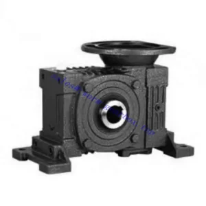
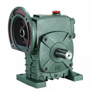
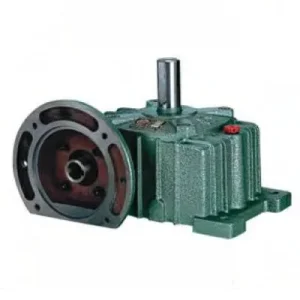
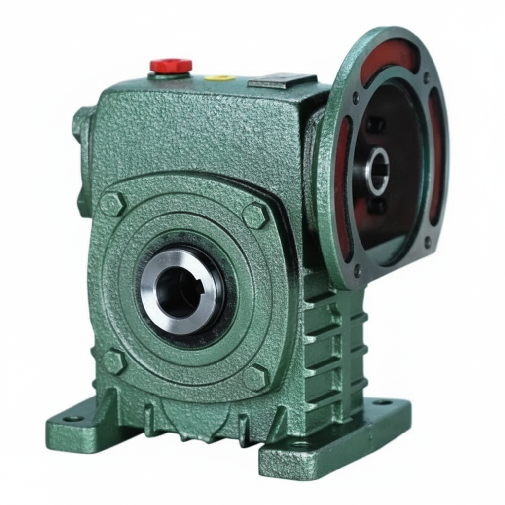
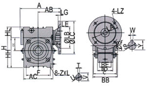
Configuration: IEC B5 Flange Input + Standard Hollow Bore Output (WK-class depth)
Motor bolts directly to input flange — no coupling. Driven shaft seats into keyed hollow bore — no output coupling. One housing, zero couplings, W-series footprint. HL at Size 100 = 80 mm.
| Size | Power (kW) | Ratio | A (mm) | B (mm) | H (mm) | HL (mm) | Flange LZ (mm) | Input Q (mm) | Output Bore S (mm) | Weight (kg) |
|---|---|---|---|---|---|---|---|---|---|---|
| 50 | 0.18 | 1/10–1/60 | 165 | 107 | 150 | 35 | 140 | 25 | Ø20 | 7 |
| 60 | 0.37 | 1/10–1/60 | 185 | 117 | 177 | 42 | 160 | 35 | Ø25 | 11 |
| 70 | 0.37/0.75 | 1/10–1/60 | 209 | 131 | 215 | 55 | 160/200 | 35/45 | Ø30 | 14 |
| 80 | 0.75/1.5 | 1/10–1/60 | 242 | 144 | 250 | 65 | 200 | 45 | Ø35 | 22 |
| 100 | 1.5 | 1/10–1/60 | 310 | 175 | 310 | 80 | 200 | 55 | Ø40 | 36 |
| 120 | 2.2/3.0 | 1/10–1/60 | 361 | 200 | 370 | 95 | 250 | 65 | Ø45 | 63 |
| 135 | 3.0/4.0 | 1/10–1/60 | 412 | 212 | 425 | 105 | 250 | 65 | Ø60 | 80 |
| 155 | 5.5 | 1/10–1/60 | 442 | 312 | 461 | 103 | 300 | 85 | Ø70 | 114 |
0.18–5.5 kW
Zero Couplings Both Ends
IEC B5 Flange Input
Hollow Bore Ø20–70 mm
W-Series Footprint
What the WDK Does That No Single WP or WK Unit Can Match
Across the W and WP families, achieving zero couplings at both ends has always required either compromising on dimensional convention or accepting a dual-unit solution. The WDK resolves this directly. Understanding the gap it fills requires comparing it against the alternatives that engineers have historically had to choose between:
| Configuration | Input Coupling | Output Coupling | Limitation |
|---|---|---|---|
| WK (through-shaft) | ✗ Required | ✓ Eliminated | Still needs input jaw coupling + coupling guard |
| FCWK (flange + hollow bore) | ✓ Eliminated | ✓ Eliminated | WP-family footprint — W-series legacy machines need baseplate mod |
| WD (flange + solid shaft) | ✓ Eliminated | ✗ Required | Solid output still needs output coupling and alignment |
| WDK ← This Unit | ✓ Eliminated | ✓ Eliminated | W-series dimensional convention — no baseplate modification |
Six Engineering Advantages Built Into the WDK Design
IEC Motor Concentricity — Input
The motor shaft and worm shaft share a machined datum — concentricity within 0.05 mm TIR. Jaw couplings allow up to 0.5 mm angular and 1 mm axial misalignment; this generates cyclic bending at input bearing frequencies that the WDK eliminates by design. Input bearing service life increases proportionally.
Shaft-Mount Output — No Alignment Step
The hollow bore slides directly onto the driven shaft and is locked with a key and locking element. No shaft coupling body to bore-fit, no coupling spider to replace, no guard to fabricate. In OEM production, this removes 45–60 minutes of alignment and assembly labour per unit compared to solid-shaft-plus-coupling configurations.
W-Series Housing — Legacy Retrofit
The WDK external housing dimensions follow the W-series convention. Foot pad bolt pattern, A-dimension, and H-dimension match existing W-series machine baseplates. Upgrading from a W-series solid-shaft unit to a WDK zero-coupling unit requires no structural modification to the machine bay or concrete plinth.
Self-Locking at ≥ 30:1 — Power-Off Hold
At ratios 30:1 and above, the worm lead angle generates effective self-locking under static loads. The hollow bore output holds the driven shaft stationary on power-off without a brake. For gravity-loaded conveyors, gate actuators, and positioning drives in Australian irrigation and food processing infrastructure, this eliminates a separate braking device.
Any IEC Motor Drops In — No Motor Base
Any IEC B5 frame motor of the correct rating bolts directly to the WDK flange face. Remote Australian sites can replace the motor from local electrical stock without a dedicated motor base or alignment jig. This is a material uptime advantage when the nearest qualified motor supplier is 200 km away and the alternative involves fabricating a custom motor bracket on site.
No Coupling Gaps — Hygiene and Safety
With no jaw couplings at either end, there are no rotating coupling bodies exposed in the machine’s working envelope. Food processing lines eliminate two coupling-gap contamination risks and two rotating guard surfaces from the machine’s occupational health assessment. Wash-down cleaning is also simplified with no coupling geometry to clean around.
Application Environments — Where the WDK’s Zero-Coupling Design Pays Off
- 📦 OEM Packaging and Conveyor Systems — Motor-Direct Shaft-Mount
For Australian packaging OEM builders standardised on W-series dimensional conventions, the WDK replaces the motor base + jaw coupling (input) and the coupling body + coupling guard (output) simultaneously. Two fabricated components per unit removed from the build. Where production volumes are 20 or more identical units annually, this is a meaningful cost and time reduction per machine. - 🌾 Agricultural Machine Electric Conversion (shaft mounted worm gearbox)
When existing tractor PTO-driven implements are converted to electric motor drive, the WDK provides the cleanest integration: IEC motor flanges directly to the reducer input; existing implement shaft goes into the hollow bore. The W-series housing fits the structural envelope that was designed around the original W-series reducer, so no frame modification is required. - 💧 Gate Actuators and Mixer Drives — Self-Locking Hold
WDK size 80–120 at 40:1–60:1 for slow-speed gate actuators in Australian irrigation infrastructure. The self-locking mechanism holds the gate stationary on power-off — no hydraulic lock required. Hollow bore mounts directly on the gate spindle shaft; IEC motor flanges directly, removing all input coupling hardware from an environment where corrosion and contamination are constant threats. - 🏭 Food Processing Lines — Hygiene-Grade Installation
WDK size 60–100 on food-grade conveyor and metering drives. No coupling bodies in the machine envelope eliminates two rotating-component hazard zones from the safety assessment. The IEC flange seals against the motor face without a gap; the hollow bore seals against the driven shaft. Suitable for regular wash-down with no coupling recess to trap moisture or product residue. - 🔄 Legacy W-Series Machine Upgrade — Zero-Coupling Retrofit
W-series machines originally specified with through-shaft solid output can be upgraded to WDK zero-coupling configuration without baseplate modification. The driven shaft bore diameter determines the WDK size; the W-series housing footprint is unchanged. The motor must be IEC B5 frame — confirm LZ, LB, and Q dimensions against the WDK flange datasheet before ordering
Drive Accessories, PTO Integration, and Components
The WDK is supplied as a standalone reducer. The following components are specified separately and must be matched to the WDK size and application before ordering:
PTO Shaft Adaptor
For agricultural applications where tractor PTO is retained as the power source, a yoke-end adaptor mounts to the IEC flange face in place of an electric motor. The adaptor must include a friction slip clutch set at 1.5× rated input torque — tractor PTO speed surges during engagement can otherwise exceed the worm gear’s peak input torque limit. See agricultural PTO shaft specifications for yoke sizing and spline configuration.
IEC B5 Motor — Frame Verification
Any IEC B5 TEFC 4-pole motor of the correct frame bolts to the WDK flange. Before ordering, confirm: (1) IEC frame number matches the LZ×LB flange bolt circle; (2) motor shaft diameter matches input bore Q; (3) motor shaft length does not exceed T×V bore depth — a bottomed-out shaft prevents correct flange seating. Record the motor IEC frame on the plant maintenance schedule for remote-site replacement planning.
Output Bore Locking Element
Standard: key + set screw for smooth continuous loads at WDK-class HL depth. For any reversing or cyclic loads, specify a shrink disc — uniform radial clamping prevents the progressive set screw loosening that repeated cyclic torques cause. Shrink discs are specified by bore diameter (S dimension) and required transmissible torque with service factor applied.
Torque Arm (Shaft-Mount Config)
In shaft-mount configuration the WDK housing is restrained by a torque arm anchored to a fixed structure. The arm must resist the combined reaction torque plus the gravitational moment of the motor-plus-reducer assembly. For WDK sizes 120–155 with motor weights of 15–35 kg, the gravitational moment is significant — specify the torque arm for combined dynamic and gravitational load, not reaction torque alone.
Oil Fill and Breather
ISO VG 220 mineral gear oil, standard orientation fill. For continuous duty at ratios 40:1+ in Australian summer ambient above 40°C, PAO synthetic ISO VG 220 extends the thermal rating by 10–15% and the service interval to 5,000 hours. Fit a pressure-equalising breather to prevent positive housing pressure from weeping oil past the bore seals during extended high-duty-cycle operation.
Thermal Sensor (Sizes 100+)
Sizes 100 and above carry an NPT sensor port. In shaft-mounted installations where the housing cannot be visually accessed during operation, a PT100 connected to SCADA provides the overtemperature protection that manual housing checks cannot reliably deliver in enclosed machine bays operating at 40°C+ ambient in north Queensland or northwest WA.
Installation Sequence — WDK Foot-Mount or Shaft-Mount
Verify IEC Frame and Bore Dimensions
Before mounting: confirm motor IEC frame against LZ, LB, LC, LE, LG flange dimensions. Confirm motor shaft diameter equals Q. Confirm motor shaft length does not exceed T×V bore depth. Confirm driven shaft diameter equals output bore S. Dimension mismatches at this stage take minutes to resolve; mismatches found after mounting take hours.
Mount Reducer on Baseplate or Driven Shaft
Foot-mount: bolt WDK housing to baseplate at Z×L foot pads using the correct grade fasteners. Shaft-mount: slide hollow bore onto driven shaft, fit key, and install torque arm to a fixed anchor point — rubber bushed to absorb vibration. Verify torque arm is not in tension or compression under full load — it should be in pure shear.
Lock Output Bore to Driven Shaft
Install key in keyway, fit locking element (set screw or shrink disc per application). Torque shrink disc bolts to the specified value in a cross pattern — two passes minimum. Apply anti-fretting compound to shaft surface before sliding bore on, to prevent galvanic fretting corrosion between steel bore and steel shaft in the contact zone.
Bolt IEC Motor to Input Flange
Insert motor shaft into input bore Q. Bring motor face to flange face — motor shaft must not contact the bottom of the bore before the motor face is flush with the flange. Torque all flange bolts evenly in a star pattern to the IEC-specified torque for the bolt grade. There is no alignment step — motor and worm shaft are co-axial by design.
Verify Oil Level and Commission
Confirm oil fill level at the fill/level plug for the installed orientation. Run under no-load for 30 minutes — check housing temperature does not exceed 70°C and there are no oil weep points at either bore seal or the flange face gasket. If thermal sensor is fitted, confirm reading within 5°C of IR thermometer reading at the housing surface.
First 500-Hour Inspection
Flush and replace oil — break-in wear particles from the bronze wheel running-in period contaminate the oil in the first 500 hours. Re-torque bore locking element and all flange bolts. Inspect bore face for any fretting powder (rust-brown oxide) that would indicate insufficient locking force. If fretting is present, increase locking element torque and re-inspect at 1,000 hours.
Maintenance Schedule — WDK Series
| Interval | Task | WDK Note |
|---|---|---|
| First 500 hr | Oil flush and replace; bore locking element re-torque; flange bolt check | Inspect bore face for fretting oxide — any rust-brown powder indicates inadequate locking force; upgrade to shrink disc before continuing |
| Every 2,500 hr | Full oil change; all seals inspection; locking element re-torque; flange bolt torque | Inspect flange face gasket for oil seep — if weeping, replace gasket; do not over-tighten flange bolts as a remedy (distorts flange seating) |
| Every 5,000 hr | Remove bore from shaft; bore zone and shaft contact inspection; bearing radial clearance | Measure bore internal diameter — if widened beyond H7 tolerance the bore must be replaced; do not attempt to restore bore size by re-boring the housing |
| Motor replacement | Verify IEC frame and shaft length before ordering replacement | Different motor manufacturers vary shaft lengths within the same IEC frame designation — always measure shaft length against T×V bore depth, not just the frame number |
For WDK bore sizing, IEC motor frame verification, torque arm load calculation, and stock availability across sizes 50–155 for Australian project schedules, the engineering team at our worm gearbox technical portal provides application-specific support. Submit your driven shaft diameter, motor power, ratio requirement, and ambient temperature for a confirmed selection recommendation. For further resources on agricultural shaft-mounted worm gearbox applications in Australian conditions, visit gearboxagricultural.com. Ready to confirm your specification? Contact our technical team via the enquiry page.