Description
Technical Specifications — WDZ Series Worm Gear Reducer
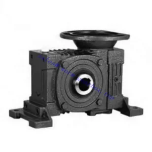
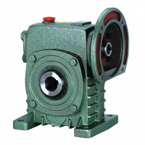
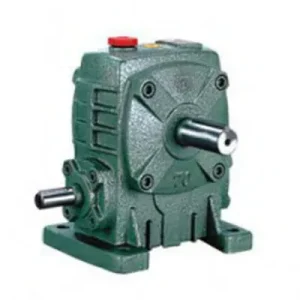
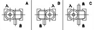
Configuration: IEC B5 Flange Input + Solid Shaft Output — W-Series Housing Convention
Motor bolts directly to IEC B5 flange — no input coupling required. Solid output shaft (S diameter, LS length) connects to driven load via coupling or sprocket. W-series dimensional footprint — existing W-series machine baseplates require no modification. Sizes 50–175, up to 7.5 kW.
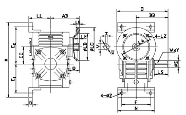
| Size | Power (kW) | Ratio | AB (mm) | LL (mm) | B (mm) | BB (mm) | CC (mm) | Flange LZ (mm) | Input Q (mm) | Output LS (mm) | Output S (mm) | Weight (kg) |
|---|---|---|---|---|---|---|---|---|---|---|---|---|
| 50 | 0.18 | 1/10–1/60 | 84 | 72 | 165 | 95 | 50 | 140 | 25 | 40 | Ø17 | 8.5 |
| 60 | 0.37 | 1/10–1/60 | 92 | 80 | 190 | 110 | 60 | 160 | 35 | 50 | Ø22 | 11 |
| 70 | 0.37/0.75 | 1/10–1/60 | 110 | 95 | 210 | 130 | 70 | 160/200 | 35/45 | 60 | Ø28 | 17 |
| 80 | 0.75/1.5 | 1/10–1/60 | 128 | 105 | 240 | 140 | 80 | 200 | 45 | 65 | Ø32 | 26 |
| 100 | 1.5 | 1/10–1/60 | 145 | 135 | 263 | 163 | 100 | 200 | 55 | 75 | Ø38 | 39 |
| 120 | 2.2 | 1/10–1/60 | 182 | 160 | 310 | 185 | 120 | 250 | 65 | 85 | Ø45 | 60 |
| 135 | 3.0/4.0 | 1/10–1/60 | 200 | 185 | 335 | 210 | 135 | 250 | 65 | 95 | Ø55 | 88 |
| 155 | 5.5 | 1/10–1/60 | 236 | 220 | 402 | 252 | 155 | 300 | 85 | 110 | Ø60 | 120 |
| 175 | 7.5 | 1/10–1/60 | 240 | 240 | 412 | 262 | 175 | 300 | 85 | 110 | Ø65 | 158 |
0.18–7.5 kW
IEC B5 Flange Input
Solid Shaft Output
W-Series Housing
No Input Coupling
WDZ in the W-Family — Where It Sits and Why
The W-family flange-input solid-shaft category contains three distinct units. Understanding where the WDZ sits relative to the others clarifies when it is the correct specification and when an alternative should be considered:
| Unit | Input Type | Output Type | Max Size | Specify When |
|---|---|---|---|---|
| W Series | Through-shaft (either side) | Solid shaft | 200 | Motor position flexibility required; coupling from either side |
| DZ Series | IEC B5 Flange (fixed face) | Solid shaft | 135 | Compact housing required; machine bay depth constrained |
| WDZ ← This Unit | IEC B5 Flange (fixed face) | Solid shaft | 175 | W-series footprint + IEC flange input + full size range to 7.5 kW |
WDZ Advantages — Motor-Direct Integration in a W-Series Machine
IEC Flange Input — No Input Coupling Ever
The WDZ IEC B5 flange eliminates the jaw coupling, coupling guard, and motor base from the input side permanently. The W-series equivalent (W Series) still requires a jaw coupling on every installation. In W-series machines undergoing maintenance simplification — removing scheduled coupling spider replacements from the PM programme — swapping to a WDZ achieves this at the same baseplate footprint. Motor concentricity is factory-set to 0.05 mm TIR; no alignment procedure required.
Size 175 at 7.5 kW — Widest W-Family Flange-Input Solid-Shaft Range
The WDZ extends to size 175 at 7.5 kW — the largest solid-shaft, IEC flange-input unit in the W family. The DZ tops out at size 135 and 3.0 kW. For Australian mining conveyor drives, large pump drives, and heavy industrial agitators built around W-series dimensional conventions that require motor-direct input at power levels above 3 kW, the WDZ 155–175 is the only W-family specification that fits the baseplate and delivers the required power without an input coupling.
W-Series Housing — Baseplate Unchanged
WDZ B dimension and foot pad bolt pattern match the W-series convention at each size number. Retrofitting from a W-series solid-shaft unit to a WDZ on the same machine requires no baseplate modification, no concrete plinth re-drilling, and no structural alteration to the machine bay. Only the motor base and jaw coupling are removed; the baseplate hardware is reused. For Australian plant engineers managing W-series machine upgrades across large fleets, this zero-modification retrofit is a significant labour saving.
Self-Locking at ≥ 30:1
At ratios 30:1 and above, the worm mesh provides static self-locking — the output shaft holds stationary on power-off without a brake. In the W-series convention where the WDZ replaces a W-series unit with a braked motor, the WDZ at these ratios eliminates the motor brake from the specification, reducing the number of components that require periodic inspection and replacement on large W-series machine fleets in remote Australian locations.
Longer Output Shaft — Better Overhung Load Margin
The W-series housing convention provides a longer LS output shaft section than the equivalent DZ at the same size number. This gives more shaft engagement length for coupling hubs, sprockets, and pulleys, and a larger overhung load (OHL) capacity from the bearing span. For chain drives with large sprockets or belt drives with significant belt tension, the WDZ’s larger OHL margin at size 100+ provides a worthwhile safety factor compared to the more compact DZ alternative.
W-Series Heat Dissipation — Better Thermal Margin
The WDZ’s larger W-series housing has proportionally more surface area for natural convection heat dissipation than the compact DZ at the same power rating. In continuous-duty Australian summer conditions at 40°C+ ambient, this larger thermal surface area provides more headroom before the thermal rating becomes the constraining factor at high ratios — a meaningful advantage on slow-speed drives where worm mesh efficiency is lower and heat generation per kW of output is highest.
Applications — W-Series Legacy Machines and New Motor-Direct Builds
- 🔄 W-Series Machine Input Coupling Elimination Retrofit (worm gear reducer)
When a W-series solid-shaft machine is upgraded to eliminate the input jaw coupling — either due to repeated coupling spider replacements, coupling alignment drift, or a maintenance simplification programme — the WDZ replaces the W-series unit on the same baseplate at the same size number. The motor base and jaw coupling are removed; the WDZ IEC flange accepts the same motor. No baseplate modification, no concrete work, no new motor required in most cases. This retrofit is the most common WDZ application across Australian industrial plant. - ⛏️ Mining and Bulk Handling — Large Frame with IEC Direct (high torque worm gearbox)
WDZ size 155–175 at 5.5–7.5 kW for large-frame mining conveyor belt drives, crusher feed conveyors, and bulk material handling equipment originally designed around W-series dimensional conventions. At these power levels, the DZ only reaches 3.0 kW (size 135) and is insufficient. The WDZ 175 delivers 7.5 kW with IEC motor direct on the W-series footprint — the only W-family specification that covers this power range without an input coupling. For further details on industrial gearbox integration in mining and bulk handling in Australia, see resources at gearboxagricultural.com. - 🌾 Agricultural Drive Upgrades — PTO to Motor Conversion
Larger W-series agricultural machinery originally driven by tractor PTO, converted to fixed electric motor drive, uses WDZ size 100–155 where the implement shaft connection is a solid shaft coupling and the machine bay was designed around W-series housing dimensions. The IEC flange accepts any standard electric motor; the W-series housing fits the existing frame without modification. Where PTO input is retained alongside electric motor backup, a yoke adaptor on the WDZ flange face accommodates both drive sources alternately. Full PTO shaft specification guidance is available at agricultural PTO shaft resources. - 💧 Water Infrastructure — Gate and Pump Drives, Self-Locking
WDZ size 80–135 at 30:1–60:1 for gate actuators and slow-speed pump drives in Australian water treatment and irrigation infrastructure. The self-locking mechanism at these ratios holds gates stationary on power-off. The W-series housing convention is often already the standard at Australian water authority infrastructure sites; the WDZ replaces W-series units without requiring any change to the site’s structural mounting hardware or motor specifications. - 🏭 New OEM Builds — W-Series Convention with Motor-Direct Input
For new OEM machine designs that adopt the W-series dimensional convention from the outset — whether for fleet standardisation, component interchangeability with legacy plant, or access to the wider W-series product family for future expansion — the WDZ provides IEC motor-direct input with no input coupling from day one. This eliminates the first scheduled coupling maintenance from the machine’s PM programme before the machine is even commissioned.
Drive Accessories and Component Selection for the WDZ
IEC B5 Motor — Larger Frame Verification at Size 155–175
Sizes 155 and 175 accommodate IEC motors in the 100–112 frame range. At these larger frames, confirm the LZ×LB flange bolt circle, Q input bore diameter, and T×V bore depth against your specific motor. Different motor manufacturers implement IEC 100–112 frames with varying shaft lengths that can differ by 10–15 mm — always measure shaft length against T×V for sizes 155 and 175 before ordering.
PTO Adaptor + Friction Slip Clutch
For agricultural drives retaining tractor PTO input, a yoke-end IEC flange adaptor mounts at the WDZ input face in place of the electric motor. The friction slip clutch (set at 1.5× rated input torque) protects the worm gear from PTO engagement surges. At WDZ sizes 100+ the worm gear rated input torque is substantially higher — confirm the slip clutch torque setting matches the specific WDZ size rated input torque, not a generic value.
Output Shaft Coupling — OHL Position Matters
The WDZ longer LS output shaft (versus DZ) gives more flexibility in coupling hub positioning. For maximum overhung load (OHL) capacity, position sprockets or pulleys as close to the housing face as the coupling hub allows — the OHL decreases as the load moves further from the housing face along the LS shaft length. Verify permissible OHL for your WDZ size and load position before finalising the drive layout.
Coupling Guard — AS 4024 Compliance
The WDZ solid output shaft requires a coupling guard on every installation compliant with AS 4024 machinery safety standards. Guard design must account for the WDZ housing dimensions and the output shaft LS length to ensure the guard fully encloses the coupling or sprocket without contacting the housing or the driven equipment. For W-series machine retrofits, the existing coupling guard may be reusable if the output shaft dimensions are unchanged.
Oil — PAO Synthetic for Size 155–175 Continuous Duty
ISO VG 220 mineral oil for standard service. For WDZ sizes 155 and 175 in continuous duty at ratios 40:1+ and 40°C+ ambient, PAO synthetic ISO VG 220 extends the service interval to 5,000 hours and raises the thermal ceiling by 10–15%. At 7.5 kW input (WDZ 175), the heat generated at high ratios is proportionally more significant — the synthetic oil’s higher film strength and thermal stability materially extend worm wheel life under these conditions.
Thermal Sensor — Sizes 100+ in Enclosed Bays
NPT sensor port at sizes 100 and above. For WDZ units installed in enclosed machine bays, mine tunnels, or enclosed processing rooms where the housing cannot be visually inspected during operation, a PT100 connected to SCADA or a local alarm panel provides the overtemperature protection that periodic manual checks cannot reliably deliver in an unattended environment.
Maintenance Schedule — WDZ Series
| Interval | Task | WDZ Note |
|---|---|---|
| First 500 hr | Oil flush; flange bolt torque check; output shaft coupling re-check | If upgrading from W-series solid-shaft, confirm the new WDZ output shaft S and LS dimensions match the coupling or sprocket hub that was used on the W-series — dimensions may differ between series despite same size number |
| Every 2,500 hr | Full oil change; all seals; coupling spider inspection; flange face gasket | Inspect IEC flange face gasket for oil weep — if the WDZ is vertical or in a non-standard orientation, oil can pool at the flange face and accelerate gasket degradation; inspect and replace proactively |
| Every 5,000 hr | Bearing radial clearance; output shaft runout; worm wheel visual at inspection cover | At sizes 155–175, output shaft runout beyond 0.05 mm TIR indicates bearing wear or housing distortion from sustained overhung load — address before continuing operation at high power |
| Motor replacement | Verify IEC frame, shaft length, and shaft diameter against WDZ flange spec | At WDZ 155–175, record the IEC frame number, manufacturer, and shaft length at installation — remote Australian sites with limited electrical stock options benefit most from this pre-confirmed replacement data |
For WDZ size selection, thermal rating verification at your ambient temperature, output shaft OHL calculation, and retrofit dimension-matching against your W-series machine, the engineering team at our worm gearbox technical portal provides application-specific support. Submit your current W-series size number, required power, ratio, and ambient temperature for a confirmed WDZ recommendation. Contact us via the technical enquiry page.