Description
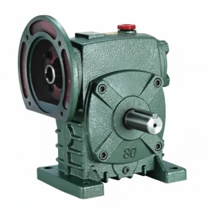
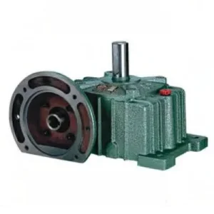
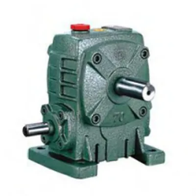
The WPA Series Single Standard Worm Gear Reducer — designated A(WPA) — is a compact, right-angle worm gearbox built to Australian industrial standards, covering a centre distance range from size 40 through to size 155. Designed for foot-mounted installations where floor space is at a premium, this series delivers reliable right-angle torque transmission across conveyors, mixers, agitators, and light-duty agricultural machinery. With gear ratios spanning 10:1 through 60:1 as standard, the WPA reducer matches demanding slow-speed, high-torque applications without the footprint overhead of helical or planetary alternatives.
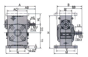
Technical Specifications — WPA Series Worm Gear Reducer
| Size | Power (kW) | Ratio | A (mm) | B (mm) | Output Shaft LS (mm) | Weight (kg) |
|---|---|---|---|---|---|---|
| 40 | 0.09 | 1/10 – 1/60 | 142 | 112 | 28 | — |
| 50 | 0.17 | 1/10 – 1/60 | 175 | 145 | 40 | 7 |
| 60 | 0.23 | 1/10 – 1/60 | 195 | 165 | 50 | 10.5 |
| 70 | 0.50 | 1/10 – 1/60 | 234 | 195 | 60 | 14.5 |
| 80 | 0.70 | 1/10 – 1/60 | 264 | 210 | 65 | 22 |
| 100 | — | 1/10 – 1/60 | 322 | 230 | 75 | — |
| 135 | — | 1/10 – 1/60 | 435 | 320 | 95 | — |
| 155 | — | 1/10 – 1/60 | 507 | 387 | 110 | — |
Right-Angle Drive
Foot Mount (WPA)
Oil-Bath Lubricated
Sizes 40 – 155
Cast Iron Housing
Why the WPA Outperforms Comparable Right-Angle Reducers
Procurement engineers across Australia consistently shortlist the WPA series for one primary reason: it solves the torque-density versus footprint trade-off without compromise. Here’s what makes it technically distinctive:
Self-Locking Geometry
At ratios of 30:1 and above, the WPA’s worm lead angle falls below the friction angle, making the output shaft non-back-drivable — a critical safety characteristic for gravity-loaded conveyors and elevator applications.
Compact Right-Angle Layout
The 90° shaft relationship allows the motor and driven shaft to occupy a single horizontal plane, dramatically reducing the structural support required compared to in-line reducer arrangements.
Cast Iron Durability
Grey cast iron housing absorbs vibration effectively in cement, mining, and materials-handling environments. Combined with a bronze worm wheel, the wear couple is deliberately mismatched to protect the more costly worm shaft.
Standardised Mounting Interface
WPA foot dimensions comply with widely adopted dimensional standards, meaning this series is a drop-in replacement for legacy reducers in Australian food processing and packaging lines with zero structural modification.
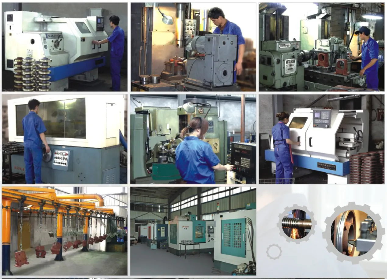
Internal Design and Material Engineering
Worm and Wheel Material Pairing
The worm shaft is precision-machined from case-hardened alloy steel, ground to DIN 3975 tooth form tolerances. The corresponding worm wheel uses a centrifugally cast phosphor-bronze ring gear, pressed and keyed onto a cast iron hub. This pairing yields a coefficient of sliding friction low enough to achieve efficiencies of 70–85% at moderate ratios (10:1–20:1), while the bronze material’s excellent conformability means minor misalignment from installation is absorbed without flank scuffing during run-in.
Bearing Selection and Radial Load Capacity
Input shafts are supported on paired deep-groove ball bearings, pre-loaded to control axial float below 0.05 mm, which is a key determinant of tooth contact pattern quality. Output shafts carry tapered roller bearings in sizes 80 and above, substantially increasing the permissible radial overhung load — relevant for chain sprocket and belt pulley drives that impose significant bending moments on the output stub.
Sealing and Lubrication
Both input and output shafts use double-lip rubber oil seals with an auxiliary dust lip, sealing the oil-bath lubrication from contamination in dusty Australian agricultural and mining environments. The internal oil volume is sized for splash lubrication at the rated input speed of 1,450 rpm; for higher-speed inputs (1,750 rpm or above), an oil-level check at 500-hour intervals is recommended. ISO VG 220 gear oil is the standard fill; EP additives are acceptable for shock-load service.
Typical Application Environments in Australia
The WPA’s combination of compact dimensions, self-locking behaviour at high ratios, and standardised foot-mounting pattern makes it a practical fit across several demanding Australian sectors:
- Grain handling & storage: Auger conveyors and grain dump hoppers use size 80–100 WPA units to achieve the 20:1–40:1 output speed reduction required at standard 4-pole motor speeds.
- Irrigation and water treatment: Right-angle drive suits in-channel gate actuators and paddle mixers in water treatment plants where the drive must be mounted above the waterline.
- Food and beverage processing: Mixer and agitator drives benefit from the self-locking property, preventing uncontrolled rotation on power loss in stirred tank reactors.
- Material handling: Overhead conveyor drives in automotive assembly and warehouse sortation lines consistently select the WPA for its low noise at slow output speeds.
- Packaging machinery: Intermittent indexing drives on rotary filling machines use size 40–60 WPA units due to their short axial length and low backlash characteristics after run-in.
Mating Components, PTO Shaft Integration & Accessories
The WPA reducer rarely operates in isolation. In Australian broadacre and horticultural applications, it is frequently combined with a PTO shaft assembly to couple tractor power to field equipment. Understanding the full drivetrain integration avoids common installation failures:
Agricultural PTO Shaft
A matched agricultural PTO shaft connects the tractor’s 540/1000 rpm PTO output to the WPA input. Telescoping cross-and-journal joints accommodate implement articulation while transmitting up to 35 Nm per mm shaft diameter.
IEC Motor Adaptor Flange
B14 or B5 flange adaptors allow direct IEC frame 63–132 motor mounting, eliminating the need for a separate motor base and flexible coupling on smaller WPA sizes.
Output Shaft Coupling
Jaw couplings (L-jaw or spider) rated for the WPA’s output torque absorb torsional shock between the reducer and driven equipment, extending worm wheel life in intermittent-duty cycles.
Breather / Vent Plug
A pressure-equalising breather replaces the standard oil filler in high duty-cycle installations, preventing positive internal pressure from forcing oil past the output shaft seal.
Torque Arm Kit
When the WPA is shaft-mounted using an optional hollow bore conversion, a torque arm anchors the housing against reaction torque, avoiding bending loads on the driven shaft.
Thermal Monitoring Sensor Port
Size 100 and above housings feature an NPT sensor port for a PT100 or thermistor, enabling SCADA-connected thermal overload protection in automated plant environments.
How to Select the Correct WPA Size for Your Application
Selecting an undersized worm gear reducer is the single most common cause of premature worm wheel failure in Australian plant maintenance records. Follow this four-step process to ensure the correct specification is submitted at the enquiry stage:
Determine the Required Output Torque
Calculate driven load torque (Nm) including peak shock multiplier (typically 1.5–2.5× for conveyors). This is your minimum rated output torque requirement. Do not use motor rated torque alone — add the gear ratio gain: T_out = T_motor × ratio × η.
Confirm the Required Output Speed
Divide motor speed by required output RPM to find the exact ratio. WPA standard ratios are 10, 15, 20, 25, 30, 40, 50, 60:1. If a non-standard ratio is needed, a two-stage arrangement may be required.
Check Thermal Rating at Duty Cycle
Worm gearboxes generate more heat than helical equivalents. At continuous duty (CDF 100%), the thermal rating (kW) from the catalogue must exceed your input power. For S2 or S4 duty, a thermal service factor is applied — typically 0.75–0.85 — reducing the effective thermal limit.
Verify Overhung Load on Output Shaft
Sprocket and pulley drives impose radial loads at the shaft extension midpoint. Cross-reference the permissible overhung load (OHL) values in the dimensional table against your calculated chain or belt pull. Exceeding OHL is the primary cause of output shaft bearing failure.
Maintenance Schedule and Service Life Expectations
A properly selected and correctly installed WPA worm gearbox should deliver 20,000+ hours of service in continuous-duty applications before worm wheel replacement is warranted. The following schedule reflects typical Australian industrial practice for maximising this interval:
| Interval | Task | Notes |
|---|---|---|
| First 500 hours | Drain and replace oil (run-in flush) | Bronze wheel debris accumulates during break-in — critical flush |
| Every 2,500 hours | Full oil change + shaft seal inspection | ISO VG 220 EP gear oil; check for seal weeping |
| Every 5,000 hours | Bearing clearance check + housing inspection | Measure output shaft radial play; >0.1 mm indicates bearing wear |
| At replacement | Worm wheel flank inspection | Pitting >10% tooth face area warrants full wheel replacement |
Installation Best Practices for Long-Term Reliability
Even a correctly selected worm gear reducer will fail prematurely if installation practices are poor. The following are the most frequent field errors observed across Australian maintenance teams, and the corrections that resolve them:
Mounting surface flatness: The four foot pads must contact a machined surface flat to within 0.10 mm across the full bolt circle. Shimming one foot corrects minor surface irregularities — do not rely on bolt torque to pull a distorted housing flat, as this introduces housing distortion that misaligns the worm gear mesh.
Output shaft radial alignment: Chain and belt drives impose overhung loads. Position the sprocket or pulley as close as practical to the housing face — within 10 mm of the seal — to minimise the bending moment arm. Every 10 mm of additional standoff doubles the bending moment on the output shaft bearing.
Mounting position and oil level: The WPA is catalogued for shaft-horizontal mounting. If the application requires shaft-vertical input or output, the internal oil volume must be recalculated. Consult your supplier for the correct oil fill level for non-standard orientations — over-filling leads to seal failure, under-filling causes accelerated worm wheel wear.
For full technical support on the WPA series and other worm gearbox models suitable for Australian industrial and agricultural applications, our engineering team is available for selection assistance. You may also find our guides on agricultural gearbox configurations useful when integrating into tractor-driven systems.