Description
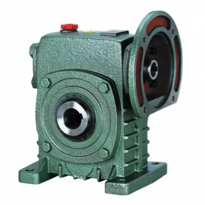
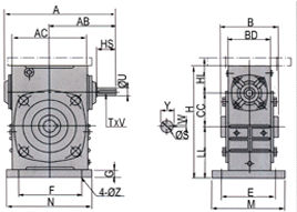
Technical Specifications — WKA Series Worm Gear Reducer
| Size | Ratio | A (mm) | AC (mm) | B (mm) | H (mm) | HL (mm) | Input HS (mm) | Output Bore S (mm) | Output Key W (mm) | Weight (kg) |
|---|---|---|---|---|---|---|---|---|---|---|
| 50 | 1/10–1/60 | 175 | 115 | 107 | 165 | 50 | 30 | Ø20 | 6 | 7 |
| 60 | 1/10–1/60 | 195 | 126 | 117 | 195 | 60 | 40 | Ø25 | 8 | 11 |
| 70 | 1/10–1/60 | 234 | 155 | 131 | 233 | 73 | 40 | Ø30 | 8 | 14 |
| 80 | 1/10–1/60 | 264 | 174 | 144 | 268 | 83 | 50 | Ø35 | 10 | 22 |
| 100 | 1/10–1/60 | 322 | 224 | 175 | 330 | 150 | 50 | Ø40 | 12 | 36 |
| 120 | 1/10–1/60 | 385 | 264 | 200 | 395 | 180 | 65 | Ø45 | 14 | 63 |
| 135 | 1/10–1/60 | 435 | 304 | 212 | 455 | 215 | 75 | Ø60 | 18 | 80 |
| 155 | 1/10–1/60 | 494 | 330 | 312 | 495 | 235 | 85 | Ø70 | 20 | 114 |
| 175 | 1/10–1/60 | 548 | 370 | 334 | 558 | 260 | 85 | Ø80 | 22 | 150 |
| 200 | 1/10–1/60 | 688 | 420 | 346 | 620 | 290 | 95 | Ø85 | 22 | 218 |
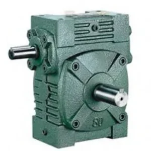
Input Shaft Dimensions — WKA Through-Shaft (Both Sides Active)
| Size | Input HS (mm) | Input U (mm) | Key T×V (mm) | Output Key Y (mm) |
|---|---|---|---|---|
| 50 | 30 | 12 | 4×2.5 | 22.8 |
| 60 | 40 | 15 | 5×3 | 28.3 |
| 70 | 40 | 18 | 5×3 | 33.3 |
| 80 | 50 | 22 | 7×4 | 38.3 |
| 100 | 50 | 25 | 7×4 | 43.3 |
| 120 | 65 | 30 | 7×4 | 48.8 |
| 135 | 75 | 35 | 10×4.5 | 64.4 |
| 155 | 85 | 40 | 10×4.5 | 74.9 |
| 175 | 85 | 45 | 12×4.5 | 85.4 |
| 200 | 95 | 50 | 12×4.5 | 90.4 |
Ratio 10:1–60:1
Deep Bore HL (WS-class)
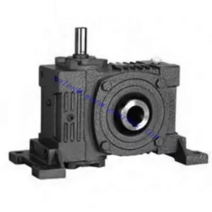
Through-Shaft Input
Bore Ø20–85mm
Shock-Rated
Why the WKA’s Deep Bore Changes the Application Envelope
The WKA and WK carry the same bore diameter at each size number. The engineering difference is entirely in the bore depth. At size 100: WKA HL = 150 mm, WK HL = 80 mm. This 88% increase in bore contact length changes three measurable outcomes:
Key Face Pressure
At the same output torque: WKA key face pressure ≈ 53% of WK key face pressure. Fretting fatigue initiates when surface pressure exceeds the material’s fretting threshold — the WKA sustains shock torques that push well beyond the WK’s fretting limit.
Micro-Slip Amplitude
The elastic deformation of the bore and shaft under load generates micro-slip between bore and shaft surfaces. A longer bore distributes this deformation over more contact area, reducing micro-slip amplitude per unit length — the primary mechanism that delays fretting corrosion onset.
Static Load Retention
The self-locking holding torque at 30:1 and above acts through the bore-shaft key connection. The WKA’s longer key engagement distributes this static load over more face area — reducing the bore fretting that occurs in shallow-bore units under sustained static gravity loads in vertical shaft applications.
WKA Advantages vs WK and vs WPKS (Cross-Family)
WS-Class Bore Depth — Shock Tolerance
WKA HL at each size matches the WPS/WPKS/FCWDS class — the deepest bore engagement available in the worm gear reducer category. At size 135, HL = 215 mm. Stone strikes on auger shafts, conveyor jam events, and emergency stops impose 3–5× rated torque — the WKA’s bore depth distributes this over sufficient key face area to prevent fretting initiation.
Motor on Either Side — Full W-Series Flexibility
The through-shaft input allows the motor coupling to be placed on either side of the housing. The WPKS (WP-family equivalent) requires a single-ended solid input stub — the WKA’s through-shaft input is structurally more flexible in legacy equipment where the motor position is constrained by existing structural elements.
Size 200 — The Largest Available
The WKA extends to size 200 with a Ø85 mm bore at HL = 290 mm and 218 kg. The WPKS (WP-family equivalent) reaches size 175 as its maximum. For large Australian mining conveyor head shafts of 85 mm diameter under shock conditions, the WKA200 is the only hollow-bore specification that provides both the bore diameter and the depth.
Self-Locking with Deep Bore Static Retention
At 30:1 and above, the worm mesh holds stationary on power-off. The WKA bore depth distributes static holding torque over 88% more key face area than the WK — reducing the bore fretting that occurs in shallow-bore units under sustained static gravity loads in vertical shaft applications or loaded hoists.
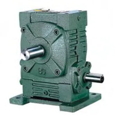
W-Series Footprint — No Baseplate Modification
External dimensions match the W series convention. Retrofitting from a W series solid-shaft unit to a WKA hollow-bore unit requires only output coupling removal and bore sliding onto the driven shaft — the baseplate, motor, and motor coupling are unchanged. For legacy W series machines that need shock-rated shaft-mount output, this is the correct zero-modification specification.
Phosphor-Bronze Wheel — Proven W-Family Gear Set
The WKA worm gear set follows the W series specification: case-hardened alloy steel worm, centrifugally cast phosphor-bronze wheel. The same gear material couple that drives the W series, WS, and FCWDS — deliberately mismatched so the bronze wheel sacrifices ahead of the hardened worm shaft in abrasive wear conditions.
Applications — Where the WKA’s Depth Justifies the Upgrade from WK
- 🌾 Grain Auger Head Shaft Drives — Stone Strike Resilience
WKA size 100–135 at 30:1 bore-mounts directly on grain auger shafts of Ø40–60 mm. Stone-strike shock events generate 3–5× rated torque. The WKA bore depth (150–215 mm) distributes this over sufficient key face area to prevent fretting. The W series through-shaft input lets the motor couple on whichever side clears the hopper structure. Australian broadacre operations report WK keyway failures within one or two harvest seasons; WKA units run for multiple seasons in the same soils. - ⛏️ Mining Conveyor Head Shaft — Large Diameter, High Shock
WKA size 155–200 handles the Ø70–85 mm head shaft diameters found on Australian mining conveyors under emergency stop and belt jam shock loads. No WP-series hollow-bore unit reaches these bore diameters — the WKA200 is the only available specification for Ø85 mm shaft at shock-rated bore depth. Motor position flexibility via through-shaft input is a practical advantage in confined underground drives where structural access determines motor side. - 🔩 Screw Conveyor Drives — Axial Thrust and Torque Combined
Screw conveyors handling cement, mineral sands, or cohesive agricultural materials generate sustained axial thrust at the head shaft plus shock torque from material bridging and restart. WKA size 100–135 handles the combined torsional shock and axial bore-end force — the deep HL provides large contact area for torsional shock; the W-series housing provides the dimensional envelope that the existing conveyor frame was designed around. - 🏗️ Winch and Hoist Drum Drives (AS 1418)
WKA size 120–155 at 20:1–40:1 for winch and hoist drum shaft drives where both emergency-stop shock loads and sustained static gravity loads apply. The deep bore distributes the emergency-stop shock torque over 215–235 mm of key face; the self-locking at 30:1+ sustains the static gravity load without bore fretting that would progressively loosen the locking connection and compromise the secondary load-holding function. - 🔄 Legacy W Series Machine Shock-Load Upgrade
When an existing W series machine running with a WK develops keyway fretting after shock load conditions are introduced (e.g., feed material changes from clean grain to stony soil, or conveyor load profile increases with belt extension), replacing the WK with a WKA at the same size number requires no baseplate modification — the W series footprint is identical. The driven shaft bore diameter is the same; only the bore depth increases. - 🚜 Agricultural PTO-to-Electric Conversion for Heavy Implements
Heavy rotary tillers, mulchers, and flail mowers converted from PTO shaft to electric motor drive need WKA size 80–120 where the implement shaft is large-diameter and the startup shock from direct-on-line motor starting requires the deep bore engagement. Through-shaft input lets the motor couple on whichever side the implement frame allows. For PTO shaft integration guidance, see PTO shaft technical resources.
Input Options and Drive Accessories for the WKA
Motor + Jaw Coupling (Standard)
Jaw coupling to either WKA input stub. On shock-load applications, select a curved-jaw coupling with polyurethane spider over a standard straight-jaw — the curved profile provides progressive shock absorption that limits the peak torque transmitted into the WKA worm gear set during start events.
PTO Shaft + Friction Slip Clutch
PTO shaft with yoke coupling to input stub + a calibrated friction slip clutch at 1.5× rated input torque. Critical for agricultural applications — stone strikes can generate instantaneous torques of 5–10× rated, which even the WKA’s deep bore cannot sustain indefinitely without a clutch as the first line of protection.
Shrink Disc — Mandatory for Shock Loads
For all WKA shock-load applications, the output bore locking element must be a shrink disc — not a set screw. Uniform radial clamping over the full WKA bore depth (150–290 mm depending on size) prevents the progressive set screw loosening that repeated shock torques cause in any bore-mount reducer regardless of bore depth.
Heavy-Duty Torque Arm (Sizes 135+)
WKA size 135 and above have 80–218 kg housing weight. In shaft-mount configuration, the torque arm must carry this gravitational moment plus the reaction torque — a dual rubber-bushed heavy-duty arm is required at these frame sizes. Specify arm and bush for combined dynamic and gravitational loading, not reaction torque alone.
Blanking Cap — Critical Seal
The unused WKA input stub is sealed with a blanking cap and lip seal. In Australian agricultural environments (chaff, dust, moisture), fit a secondary labyrinth dust cap. Inspect and replace the lip seal at every 2,500-hour oil change — failed blanking cap seals are the primary contamination path that causes worm wheel bronze degradation in W-family units.
PAO Synthetic Oil (High Ratio, Hot Ambient)
At ratios 40:1+ in continuous duty in 40°C+ Australian summer ambient, PAO synthetic ISO VG 220 extends the thermal rating by 10–15% and service interval to 5,000 hours. For WKA units on agricultural conveyors that cannot be easily stopped for oil changes during harvest campaigns, the extended interval is a meaningful operational benefit.
Maintenance Schedule — WKA Deep Bore Configuration
| Interval | Task | WKA-Specific Note |
|---|---|---|
| First 500 hours | Oil flush; shrink disc re-torque; blanking cap seal check | Inspect bore-shaft contact zone: no fretting powder expected at WKA depth under correct locking force — any powder in first 500 hours indicates inadequate shrink disc torque, re-torque immediately |
| Every 2,500 hours | Full oil change; all seals; shrink disc bolts cross re-torque | Replace blanking cap lip seal proactively; inspect active input shaft seal — both are high contamination risk points in Australian agricultural environments |
| Every 5,000 hours | Remove bore from shaft; bore zone inspection; bearing radial play | WKA deep bore means fretting progression is slower than WK at same torque — but a single 5× shock event can still initiate fretting at the bore faces; inspect regardless of operating history |
| After any jam event | Worm wheel and bore inspection before return to service | Even WKA’s deep bore cannot sustain unprotected 8–10× rated shock events — always inspect after a jam before resuming production regardless of apparent external condition |
| At worm wheel replacement (sizes 175–200) | Measure bore diameter and verify concentricity | At sizes 175–200 the bore is large enough that even minor fretting widens it beyond H7 tolerance; confirm bore diameter within 0.05 mm of nominal before fitting replacement wheel — otherwise the bore concentricity problem transfers to the new wheel |
For WKA bore size selection, shrink disc specification, torque arm combined load calculations, and size 175–200 procurement planning, the engineering team at our worm gearbox technical portal provides application-specific support including dimensional drawings and bore engagement length calculations. For agricultural shock-load applications, contact us via the technical enquiry page with your driven shaft diameter, load torque, and shock factor. For agricultural gearbox integration resources, visit gearboxagricultural.com.