Description
Technical Specifications
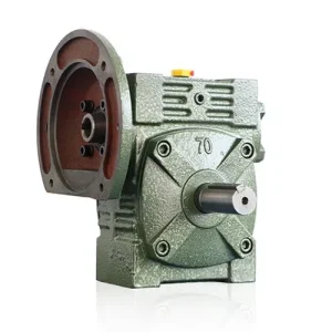
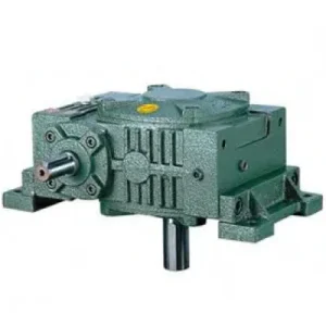
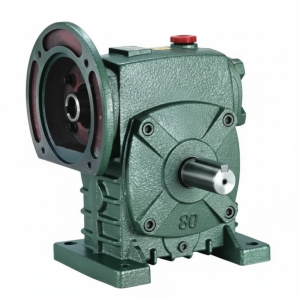
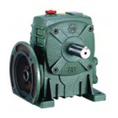
The WPDA series worm gear reducer shares the rugged WPA housing architecture while adding a purpose-machined motor adaptor face on the input. This design eliminates coupling brackets, reduces misalignment risk, and allows the motor and reducer to be handled as a single gearmotor assembly — significantly reducing machine builder installation time. Single-stage speed ratios span 10:1 to 60:1; double-stage configurations through pairing with a second WPDA unit achieve 200:1 to 3,600:1.
| Parameter | Range / Value | Notes |
|---|---|---|
| Frame Sizes | 40 – 175 | 11 standard sizes |
| Single-Stage Ratio | 10:1 – 60:1 | Standard range |
| Double-Stage Ratio | 200:1 – 3,600:1 | Tandem configuration |
| Output Torque (max.) | Up to 2,500 N·m | Size 175 |
| NEMA Motor Frames | 56C – 250TC | Size-dependent |
| Worm Material | 45# Steel (HT) | Surface-hardened |
| Wheel Material | Tin Bronze | ZCuSn10Pb1 |
| Housing | Cast Iron HT200 | Ribbed for cooling |
| Accessories Included | Breather plug + oil sight glass | Standard fit |
| Certifications | ISO 9001 / CE / SGS | Quality assured |
Performance Strengths That Distinguish the WPDA Platform

The WPDA is based on years of field-proven design refinement. Its tooth surface geometry was developed using contact analysis software to maximise the load-bearing area across the worm–wheel mesh, delivering torque transfer performance that comfortably exceeds commodity catalogue specifications. For buyers who have struggled with premature bronze wheel pitting on cheaper alternatives, the WPDA’s conjugate tooth profile and carefully controlled hobbing pass represent a measurable upgrade.
Three features particularly stand out against competing products in the Australian market:
Heavy-Duty Bearing Arrangement
Preloaded bearings on both shafts handle combined radial and axial loads common in conveyor and mixer duty without need for external bearing housings.
Minimal Backlash at Rated Load
The sliding engagement characteristic of the worm drive naturally limits backlash through friction, benefitting positioning applications that would otherwise require expensive zero-backlash couplings.
Built-In Oil Level Monitoring
The standard-fit oil sight glass and breather plug address the two most common field failures — oil starvation and seal push-out from internal pressure — without requiring external modification.
Direct Motor Face-Mount
The machined NEMA adaptor face accepts 56C through 250TC motor frames, eliminating coupling brackets, motor support rails, and parallel misalignment corrections during commissioning.
Understanding the High-Ratio Worm Gear Transmission Mechanism

The high ratio worm gearbox achieves its large speed reduction because each full rotation of the single-start worm advances the worm wheel by exactly one tooth pitch. A 60-tooth wheel therefore requires 60 worm revolutions per wheel revolution — giving a 60:1 ratio from a single, compact right-angle stage. Multi-start worms (2 or 3 starts) increase efficiency at the cost of reduced ratio per stage and reduced self-locking tendency.
Efficiency & Heat Losses at Different Ratios
Transmission efficiency in a worm drive is a direct function of the lead angle: single-start worms at 60:1 achieve approximately 60–65% efficiency under full load, while 10:1 ratios using multi-start worms reach 85–90%. This efficiency gap explains why the thermal rating (the continuous input power the housing can dissipate without oil overheating) becomes the binding constraint for high-ratio applications on continuous duty cycles. The WPDA’s ribbed cast iron housing and standard breather plug are both dimensioned to address this thermal challenge at the design’s rated power envelope.
Double-Stage Configurations for Ultra-Low Output Speeds
When process requirements call for output shaft speeds below 5 rpm — common in solar tracker azimuth drives, rotary kiln trunnions, or slow-speed agitators — two WPDA units can be cascaded to produce combined ratios from 200:1 to 3,600:1. The primary reducer output shaft drives the secondary input shaft through a solid coupling, halving the secondary unit’s input speed before the second worm stage multiplies reduction again. This arrangement maintains the compact right-angle output geometry and retains the self-locking characteristic at the final output shaft.
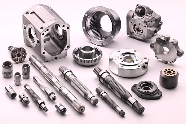
WPDA Internal Architecture & Key Accessories
The WPDA is a fully integrated power transmission unit. The following sub-assemblies work in concert to deliver reliable, long-life performance:
Heat-Treated 45# Steel Worm
The induction-hardened worm thread runs at surface hardness 56–62 HRC. The through-hardened core retains impact toughness against shock loads from motor start-up transients and load reversals. Thread geometry is precision-ground after hardening to eliminate deformation-induced profile errors that increase contact stress and reduce tooth life.
Conjugate Tin Bronze Worm Wheel
Hobbed with a tool geometry identical to the mating worm profile, the ZCuSn10Pb1 bronze wheel achieves full conjugate action across the contact zone. The lead of the bronze in the alloy provides a self-lubricating boundary film that prevents seizure during oil starvation transients — a common failure event in systems with faulty breather plugs or degraded seals.
Motor Adaptor Flange (NEMA / IEC)
The NEMA C-face adaptor is machined in the same fixture as the housing bore, guaranteeing concentricity within 0.05 mm TIR. This eliminates the angular misalignment that damages motor bearings and coupling elastomers when separate adaptor plates are bolted after machining. Compatible motor frames range from 56C (size 40) through 250TC (size 175).
Oil Sight Glass & Breather Plug (Standard)
Unlike many competitors who treat these as optional extras, the WPDA ships with both items fitted as standard. The sight glass allows oil level verification without removal of the drain plug — critical for monthly inspections in installations where oil loss from seal deterioration may not be immediately visible. The breather plug equalises internal pressure during the thermal breathing cycle to prevent seal extrusion.
Output Shaft & Hollow Bore Options
Standard output is a solid keyed shaft. Optional hollow bore output (with shrink disc or keyway) allows direct mounting onto a driven machine shaft, eliminating the driven-side coupling entirely — popular in conveyor drive stations and pump drive arrangements where shaft-to-shaft spacing is restricted.
Thermal Extension & External Cooling Options
For continuous duty at high load fractions or tropical ambient conditions, an external cooling fan kit or water-cooled jacket can be retrofitted to the housing exterior. This extends the thermal rating by 30–50% without changing the mechanical envelope, enabling a smaller frame size to meet duty requirements that would otherwise demand the next model up.
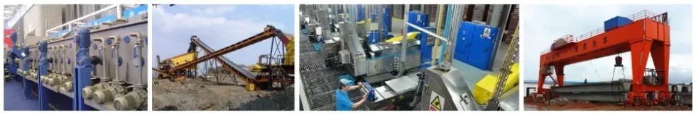
Primary Applications of the WPDA Compact Worm Gearbox
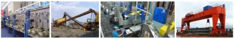
The WPDA’s compact motor-to-gearbox package suits any application where installation space is restricted and the designer needs to avoid a separate motor mounting structure. Its most common deployment environments include:
| Industry Sector | Typical Machine | Key Requirement Addressed |
|---|---|---|
| Plastics & Rubber | Extruder feed screws, mixing lines | Sustained high-torque at 5–30 rpm |
| Metallurgy | Ladle tilting, rolling mill table drives | Self-locking position hold, shock resistance |
| Chemical Processing | Agitators, dosing screw conveyors | Low speed, corrosion-tolerant exterior |
| Lifting & Hoisting | Platform lifts, scissor tables | Self-locking at ≥30:1 ratio, compact size |
| Wastewater Treatment | Bar screen drives, aerator paddle drives | Continuous duty, sealed housing, moisture resistance |
| Solar & Renewable | Solar tracker azimuth and elevation drives | Ultra-low speed, self-locking wind-load holding |
For agricultural machinery requiring integration with a primary power take-off connection, the WPDA pairs directly with agricultural PTO shaft systems to drive stationary equipment from tractor hydraulic or mechanical output.
Installation, Commissioning & Troubleshooting the WPDA
Correct Mounting Position
The WPDA is designed for a specific mounting position that ensures the worm thread is fully submerged in the oil sump during operation. Mounting the unit in a non-recommended orientation — for example, with the output shaft pointing vertically upward — displaces the oil sump relative to the mesh zone, causing boundary lubrication on the worm thread during start-up. All non-standard mounting orientations require an oil quantity adjustment per the orientation chart supplied with each unit.
Break-In Period
New units benefit from a 100-hour break-in phase at 50–70% of rated load to allow the worm thread and bronze wheel tooth surfaces to develop a fully conformal contact patch. Oil temperature will typically run 5–10 °C higher than steady-state during this period as asperities are removed from the surfaces. A first oil change at 300–500 hours removes metal particles generated during break-in and is important for achieving full design life.
Common Field Issues & Solutions
Excessive operating temperature
Check oil grade (too high viscosity at startup), verify breather plug is clear, and check duty cycle against thermal rating. Add external fan if thermal capacity exceeded.
Output shaft seal leaking
Typically caused by positive internal pressure from blocked breather plug. Replace the lip seal and clear the breather — seal replacement alone without breather service will repeat within weeks.
Unusual gear noise
Metallic knocking indicates bearing wear; high-frequency whining points to worm thread wear or oil foam. Drain and inspect oil for metallic swarf as a first diagnostic step.
For comprehensive maintenance documentation and installation guides, the product homepage provides downloadable technical sheets for all WPDA frame sizes. Engineering support for non-standard applications is available from our team.
Procurement, Lead Times & OEM Custom Services
Standard WPDA configurations — covering all 11 frame sizes across the 10:1 to 60:1 ratio range with NEMA adaptor plates for the most common motor frames — are held in production-ready inventory. Lead times for standard orders are 5–10 business days ex-works. For Australian buyers with immediate requirements, select frame sizes are available in-region through distribution partners.
Custom services available with 2–4 week production lead time include: special shaft diameters or extended shaft lengths, non-standard keyway or spline profiles, stainless steel shaft extensions for food-grade environments, epoxy or polyurethane external coatings for chemical exposure, and custom input flange patterns for non-NEMA motor frames. All custom orders include a full dimensional report against the approved drawing before shipment. Contact the engineering and sales team with your motor frame, required output speed, load torque, and duty cycle for a rapid specification recommendation.