Description
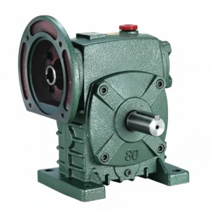
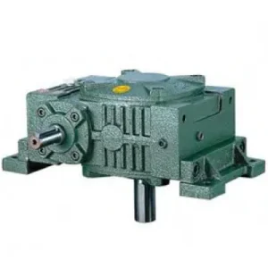
The WPS Series Single Standard Worm Gear Reducer — known in the trade as the WPS — is the extended-capacity sibling in the WP family, scaling from size 40 through to size 250 and beyond. Where the WPA addresses compact foot-mounted installations, the WPS series adds a substantially larger output shaft section and increased centre distance at each size step, delivering considerably higher output torque for the same frame envelope. This makes it the preferred worm gear reducer for medium-duty Australian industrial machinery: screw conveyors, agitated tanks, automated gate drives, and rotary-tiller geartrains where the output shaft must sustain meaningful overhung chain or belt loading without deflection.
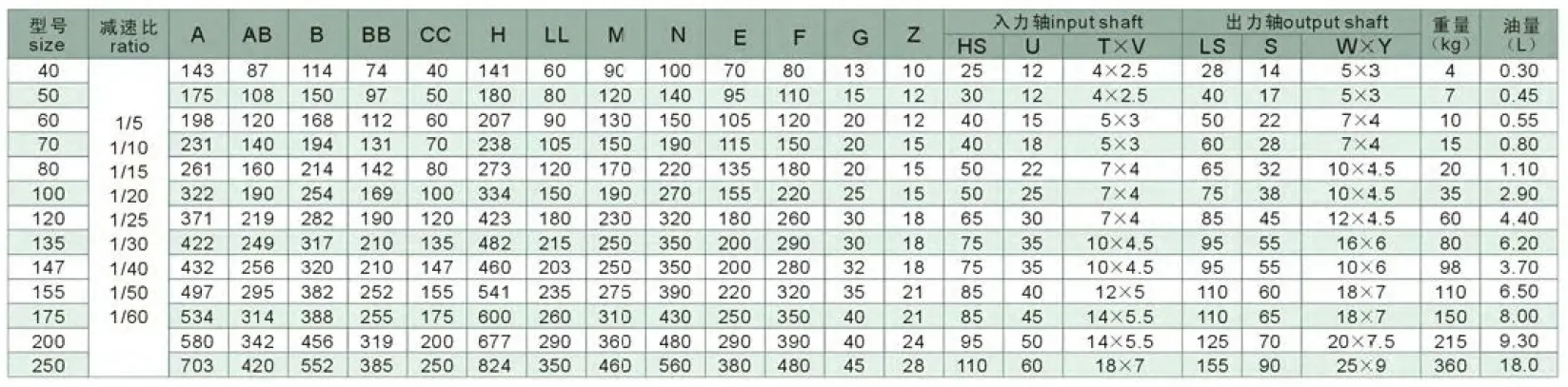
Technical Specifications — S Series (WPS) Worm Reducer
| Size | Input Power (kW) | Ratio Range | Centre Dist. A (mm) | Overall Length B (mm) | Output Shaft LS (mm) | Weight (kg) |
|---|---|---|---|---|---|---|
| 40 | — | 1/10 – 1/60 | 142 | 112 | 28 | 3.8 |
| 50 | 0.4 | 1/10 – 1/60 | 175 | 145 | 40 | 7 |
| 60 | 0.5 | 1/10 – 1/60 | 195 | 165 | 50 | 10.5 |
| 70 | 0.7 | 1/10 – 1/60 | 234 | 195 | 60 | 14.5 |
| 80 | 1.1 | 1/10 – 1/60 | 264 | 210 | 65 | 22 |
| 100 | 2.3 | 1/10 – 1/60 | 322 | 230 | 75 | 36 |
| 120 | 4.5 | 1/10 – 1/60 | 385 | 285 | 85 | 63 |
| 135 | 6.0 | 1/10 – 1/60 | 435 | 320 | 95 | 80 |
| 155 | 6.2 | 1/10 – 1/60 | 507 | 387 | 110 | 114 |
| 175 | 8.0 | 1/10 – 1/60 | 550 | 407 | 110 | 150 |
| 200 | — | 1/10 – 1/60 | 670 | 480 | 125 | — |
Ratios: 10:1 – 60:1
Right-Angle Drive
Foot-Mounted (WPS)
Input up to 8+ kW
ISO VG 220 Oil-Bath
The WPS Advantage: Higher Torque in the Same Space Envelope
In Australian plant engineering, space is often the binding constraint. The WPS series addresses this by enlarging the output shaft bearing span and worm wheel face width relative to the WPA at the same nominal size, extracting more torque from the same gear centre distance. Here’s what that translates to operationally:
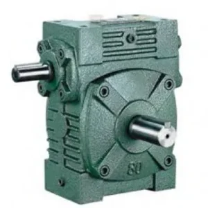
Extended Output Shaft Section
The WPS output shaft is longer and of greater diameter than the equivalent WPA at the same size, increasing the permissible overhung load rating. This matters directly for sprocket-driven conveyors, where chain pull commonly reaches 3–5× the rated output torque divided by the sprocket pitch radius.
Improved Thermal Capacity
The WPS housing has a larger external surface area than the WPA at corresponding sizes, increasing the natural convective cooling capacity. This is practically significant in continuous-duty Australian summer conditions where ambient temperatures routinely reach 38–45°C in shed environments.
Wider Size Range
The WPS series extends to size 250 and above, handling input power levels suitable for heavy conveyors and irrigation pump drives that exceed what smaller worm reducer families can accommodate, without stepping up to a more complex helical or planetary architecture.
Multi-Position Mounting
The WPS housing is machined on four orthogonal faces, enabling foot-mounting in four different orientations without modification. This flexibility simplifies plant layout in retrofit projects where drive alignment is constrained by existing structure.
Engineering Construction and Material Specification
Worm Gear Set — Geometry and Tolerance Class
The S series worm gear mesh is manufactured to DIN 3975 quality class 7 for the worm, with the worm wheel tooth form produced by hobbing with a matching hob geometry. This approach ensures correct conjugate contact across the full tooth height, rather than the approximated contact achieved when a cylindrical hob cuts a worm wheel tooth form. In practice, this means the WPS achieves measurably better load distribution across the wheel face — typically 60–70% effective face contact width versus 40–50% in lower-specification alternatives — directly translating to higher dynamic torque capacity and reduced heat generation per unit of power transmitted.
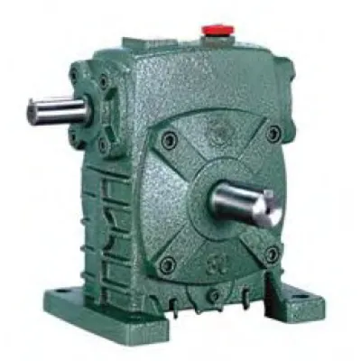
Housing and Surface Treatment
Grey cast iron (Grade 250 equivalent) is the standard housing material across the WPS range. Bores are finish-machined to H7 tolerance, ensuring correct bearing outer race seating without requiring adhesive retention compounds. External surfaces receive an epoxy primer followed by a single-pack alkyd enamel topcoat in standard RAL 7031 (blue-grey), rated for mild outdoor exposure. For salt-spray or chemical wash-down environments — common in Australian aquaculture and food processing installations — a powder-coat finish over zinc phosphate pretreatment is available as a non-standard option.
Shaft Material and Key Connection
Both input and output shafts are manufactured from 42CrMo4 (equivalent to AS 1444 Grade 4140) alloy steel, heat-treated to 28–32 HRC core hardness. The worm shaft surface is further induction hardened to 58–62 HRC and cylindrical-ground to achieve Ra ≤ 0.8 µm, which is the prerequisite for adequate oil film formation at the worm-wheel mesh. Keyways are broached to DIN 6885 Form A, and key fit is H9/h9 — providing the correct running fit without the fretting corrosion risk associated with interference key fits on output shafts exposed to reversing torque.
Where the WPS Series Solves Real Australian Engineering Problems
The WPS is not a general-purpose reducer selected purely on catalogue size. Each of the following application fits reflects a specific engineering characteristic of the S series that makes it the technically correct choice:
- 🌾 Rotary Tiller and PTO-Driven Implements
The WPS size 100–135 is a common fit for bevel-box outputs driving rotary tiller shafts in Australian market-garden and broadacre applications. The high overhung load rating suits the eccentric loading from tiller blade impact, and the sealed housing resists the fine-particle soil contamination that destroys open-gear drives. See also our resource on agricultural gearbox selection for combined bevel and worm drive arrangements. - 🏗️ Screw Conveyors for Grain and Cement
Size 120–155 WPS units are favoured for screw conveyor drives because the high gear ratio (40:1–60:1) directly from the motor eliminates an intermediate V-belt stage, reducing maintenance touchpoints. The self-locking characteristic prevents the screw from freewheeling back under full-column grain loading on shutdown. - 💧 Irrigation Channel Gate Actuators
Right-angle output geometry suits headstock-mounted gate actuator arrangements where the motor axis must be vertical (flood protection) while the gate lift shaft is horizontal. Size 80–100 WPS with stainless steel output shaft extensions handles the corrosive water-contact environment common in New South Wales and Queensland irrigation infrastructure. - 🔩 Agitator and Mixer Drives
Stirred tanks in winery, dairy, and chemical manufacturing typically require slow shaft speeds (15–60 rpm) from standard motor inputs. The WPS delivers these ratios in a single reduction stage, and the inherent self-locking behaviour prevents free impeller rotation during batch changeover — an important CIP (clean-in-place) safety characteristic. - 🏭 Material Handling and Overhead Conveyors
Overhead chain conveyors in automotive assembly plants commonly use WPS size 60–80 units driving the chain drive sprocket through a torque-arm mounted arrangement. The low noise characteristic at slow output speeds is particularly valued in assembly environments where operator communication matters.
PTO Shaft Integration and Related Drive Components
In Australian agricultural contexts, the WPS reducer is frequently positioned in the drivetrain between a tractor PTO output and a field-mounted implement. Matching the correct PTO shaft assembly to the WPS input specification is critical for reliability:
PTO Shaft (540/1000 rpm)
A telescoping cross-universal-joint PTO shaft connects tractor output to the WPS input flange. Shaft length must allow for implement articulation without the inner and outer tubes bottoming out — minimum 1/3 overlap at full extension is the accepted practice.
Friction Slip Clutch
A calibrated friction slip clutch between the PTO shaft and WPS input protects the worm gear set from torque spikes caused by soil rock strikes or soil bridging in auger conveyors. Set the slip torque at 1.5× the WPS rated input torque at the selected ratio.
Bevel Input Stage
Where the tractor PTO axis is co-linear with the intended implement drive shaft, a bevel gearbox input stage changes the axis orientation before entering the WPS reducer, allowing the correct right-angle drive layout for the implement.
Flexible Jaw Coupling
On electric motor-driven WPS installations, a jaw coupling with polyurethane spider element absorbs torsional shock from DOL motor starts, reducing the instantaneous torque spike imposed on the worm tooth flank at startup — a common failure initiation point.
Torque Limiter with Indicator
For automated plant where operator observation is limited, a torque limiter with a position indicator flag provides visual confirmation of a slip event without requiring the line to be stopped for inspection after every torque spike.
Cooling Fan / Radiator Fin Kit
For size 155 and 175 WPS units operating at continuous duty above 30°C ambient, a clip-on aluminium fin kit increases the effective housing radiation area by up to 40%, extending the thermal rating without resorting to forced oil circulation.
Managing Thermal Load: The Critical Variable in WPS Application
Worm gear efficiency is ratio-dependent, and this directly drives the thermal load the housing must dissipate. At 10:1 ratio, a single-enveloping worm mesh operating with a well-machined bronze wheel typically achieves 88–92% efficiency. At 60:1, the same mesh configuration drops to 55–65% — meaning 35–45% of input power appears as heat in the lubricant and housing rather than useful output torque.
For Australian engineers specifying the WPS at high gear ratios for continuous duty, the thermal rating (P_th) rather than the mechanical rating (P_1) is typically the binding selection constraint. P_th is calculated as:
where k_s ≈ 14–17 W/m²·K (natural convection, cast iron)
T_oil_max = 90°C (mineral oil) or 100°C (synthetic)
T_ambient = 40°C (Australian summer, enclosed shed)
In practice: at 40:1 ratio and 40°C ambient, a size 120 WPS typically has a thermal limit of approximately 2.8 kW input — well below its mechanical rating of 4.5 kW. Synthetic PAO gear oil (ISO VG 220 synthetic) increases k_s slightly and extends oil change intervals, recovering roughly 10–15% thermal headroom in this scenario.
Specifying Your WPS Order: Configuration Options
A Mounting Position
- Input horizontal, output horizontal (standard)
- Input vertical, output horizontal
- Input horizontal, output vertical (up or down)
- All positions — oil fill level changes required
B Output Shaft Configuration
- Single output shaft (standard)
- Double-ended output shaft
- Hollow bore (shaft-mount option)
- Keyed or keyless taper-lock bore
C Input Configuration
- Solid input shaft (standard)
- IEC B5 or B14 motor flange
- NEMA C-face adaptor
- PTO stub with splined bore
D Lubrication & Sealing
- Mineral ISO VG 220 (standard, pre-filled)
- Synthetic PAO VG 220 (extended interval)
- Double-lip seals both shafts (standard)
- Labyrinth + lip seal (wet/wash-down)
Diagnosing Common WPS Field Failures
When a WPS reducer shows signs of distress, the failure mode itself is diagnostic. Rather than simply replacing a worn wheel, understanding the root cause prevents recurrence:
| Symptom | Most Likely Cause | Corrective Action |
|---|---|---|
| Bronze wheel pitting within 2,000 hours | Thermal overload / insufficient oil | Verify thermal rating vs actual duty; switch to synthetic oil; add cooling fin kit |
| Oil leaking from output shaft seal | Positive housing pressure (vent blocked) | Clear or replace breather vent plug; inspect seal lip for heat damage |
| Noisy operation (grinding tone) | Worm mesh misalignment or bearing wear | Check output shaft radial play; inspect worm tooth contact pattern with marking compound |
| Vibration through housing | Excessive overhung load / worn bearings | Reposition sprocket/pulley closer to housing; replace tapered roller bearings |
| Overheating (housing > 80°C) | Ratio mismatch / continuous overload | Verify actual load vs rated thermal capacity; step up one frame size if persistent |
For technical support across the full WP series range, visit the worm gearbox specialists at our main technical portal. Our Australian-focused engineering team can provide selection calculations, dimensional drawings, and application-specific recommendations. To initiate a project discussion, visit our contact page with your application datasheet.