Description
Technical Specifications
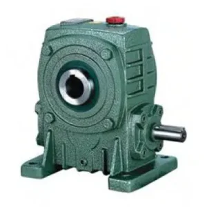
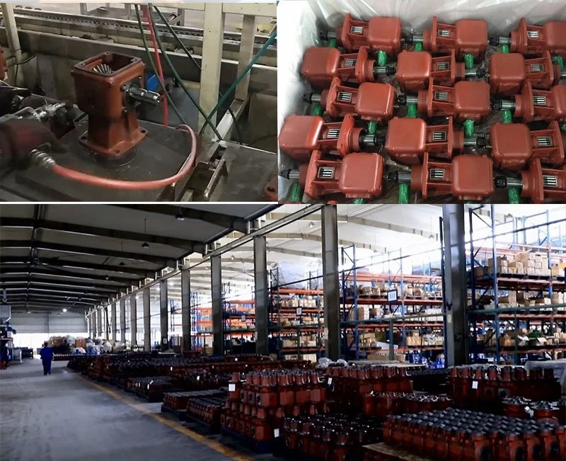
The WPS series worm gear speed reducer is engineered around a hollow bore input design that accepts standard motor shafts directly — bypassing the coupling bracket and input shaft assembly entirely. This configuration delivers the lowest centre-to-centre distance between motor and driven shaft of any WP-family unit, making the WPS the preferred selection for machine builders optimising panel or frame weight. Twelve sizes from 40 to 250 cover input power from 0.12 to 33.2 kW and output torques to 2,745 N·m.
| Parameter | Range / Value | Notes |
|---|---|---|
| Frame Sizes | 40 – 250 | 12 standard sizes |
| Gear Ratio | 10:1 – 60:1 | Single stage |
| Input Power | 0.12 – 33.2 kW | Size 40–250 |
| Output Torque | 19 – 2,745 N·m | Size-dependent |
| Weight Range | 4 – 369 kg | Size 40 – 250 |
| Worm Material | 45# Steel, HT | Surface-hardened |
| Wheel Material | Tin Bronze | Good wear resistance |
| Housing Material | Precision Cast Iron | Lightweight, non-rusting |
| Input Configuration | Hollow bore (motor shaft direct) | WD architecture |
| Shaft Orientation | Right angle (90°) | Standard |
| Lubrication | Oil bath | ISO VG 220/320 |
| Certifications | ISO 9001 / CE / SGS | Quality assured |
Six Engineering Advantages That Define the WPS Performance Profile

The WPS is more than a mounting variation of the standard WP series — the hollow bore input design required a full re-analysis of input-side bearing loads, housing wall thickness, and oil lubrication circuit to ensure the worm thread receives adequate lubrication regardless of whether the motor shaft extends partially or fully into the gearbox. Six performance attributes stand out:
Precision Lightweight Cast Iron
High-quality precision cast iron housing provides rigidity without excess mass — critical where mounting frame capacity limits gearbox weight.
High Reduction Ratio, High Efficiency
Single-stage ratios to 60:1 without compound staging — preserving energy efficiency and reducing overall drivetrain heat compared to multi-stage alternatives.
Low Noise & Stable Transmission
Worm–wheel sliding contact naturally damps vibration; output torque fluctuation is far lower than equivalent helical or spur stages — valuable in food-grade and pharmaceutical environments.
High Heat-Radiating Efficiency
The ribbed housing profile maximises convective surface area relative to internal volume, extending the operating thermal envelope without forced cooling in most duty applications.
Minimal Installation Footprint
Direct motor shaft engagement eliminates coupling brackets and intermediate shafts, allowing the motor-gearbox assembly to fit spaces up to 30% shorter than equivalent shaft-coupled configurations.
High Overload Capacity
Bronze worm wheel elastically absorbs impact loads in conveyor jam events without tooth cracking, providing overload capacity headroom beyond the rated static torque during transient events.
Understanding the WD Architecture Behind the WPS Design

The WD designation within the WPS model name refers to the dead-shaft (hollow bore) input configuration, which represents a fundamentally different structural approach from the WPA’s solid input shaft. In the WD layout, the motor shaft projects into the gearbox hollow bore and is locked through a keyway-and-setscrew arrangement. The gearbox bearings support the worm shaft concentrically around the motor shaft, meaning the motor’s own bearings carry the radial load of the worm shaft’s overhung weight at the input end.
This interdependency means correct motor bearing selection is part of the system design process for WPS installations: the motor must be rated to carry combined motor rotor weight plus the half-weight of the worm shaft and associated bearing preload at the coupling end. For motors rated to IEC 60034-14 vibration class A, this overhung load is typically well within tolerance for the common WPS frame sizes — but for oversized motors mounted on small WPS units, an intermediate bearing support bracket is recommended.
Why the Industrial Worm Gearbox Remains Preferred Over Helical Alternatives
For applications requiring ratios above 10:1 in a single stage with a 90° shaft direction change, no common gear type competes with the industrial worm gearbox on cost and compactness. Helical-bevel stages can achieve comparable ratios and higher efficiency, but at significantly greater housing size and procurement cost — typically 3–5× higher. Planetary stages offer high torque density but cannot inherently change shaft direction and lose the self-locking characteristic entirely. The WPS occupies the productivity-maximising intersection: low cost, compact, quiet, and inherently braking at high ratios.
WPS Internal Components, Accessory Options & Related Parts
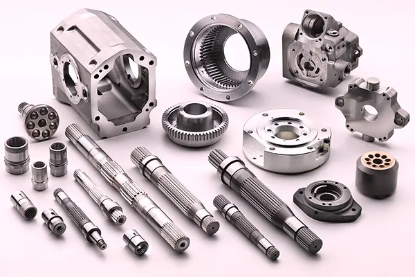
The WPS assembly consists of the following key sub-assemblies. Understanding the role of each component helps maintenance teams identify the correct replacement part and perform targeted condition monitoring rather than reactive full-unit replacements.
Hollow Bore Worm Shaft (WD Input)
The worm shaft is bored through its central axis to receive the motor shaft. A keyway and clamping setscrews lock the motor shaft engagement. The bore diameter and keyway dimensions correspond to the NEMA or IEC motor shaft standard for the compatible motor frame sizes. The worm thread is machined and ground after boring to eliminate thermal distortion of the bore as a result of thread grinding.
Tin Bronze Worm Wheel
Cast from ZCuSn10Pb1 tin bronze alloy, the worm wheel is hobbed to conjugate geometry matching the worm. The wheel hub interfaces with the output shaft through a standard parallel key — replaceable independently of the output shaft in the field using standard tooling. Replacement wheels are stocked for all 12 frame sizes across the full ratio range.
Output Shaft (Solid Keyed)
The output shaft exits the housing at 90° to the motor shaft axis in the standard WPS configuration. Diameter and keyway dimensions follow the WPS series dimensional standard (S and LS parameters from the specification table). A double-lip rotary seal protects the shaft exit from dust and moisture ingress in the Australian outdoor environments where many conveyor and agricultural applications operate.
Deep-Groove Ball Bearings (Input & Output)
Both shafts run in preloaded deep-groove ball bearing pairs. Input-side bearings are selected to handle the combined radial load from the worm tooth contact force plus the overhung motor shaft weight. Output-side bearings are sized for the full output radial and axial load combination generated by the driven machine — be it a sprocket, pulley, or coupling.
Mounting Options — Foot, Flange & Torque Arm
Standard WPS units ship with integrated foot pads for horizontal surface mounting. Optional flange-mount configurations adapt the housing for vertical or inclined installations. For shaft-mounted configurations where the gearbox rides directly on the driven shaft, a torque-arm bracket prevents housing rotation — common in conveyor head drive stations and mixing shaft applications.
Related Drive System Components
The WPS integrates naturally with standard drive train elements including: V-belt sheaves and sprockets on the output shaft for secondary speed adjustment, inline torque limiters to protect against sudden jam loads, speed sensors mounted on the output shaft extension for process control feedback, and motor-mounted frequency inverters for variable-speed WPS operation. For drive system integration involving bevel gear transmission systems, the WPS output shaft can also feed a bevel stage for multi-directional power distribution in complex machine architectures.
Real-World Applications of the Right-Angle Worm Gearbox Across Industries
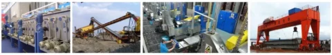
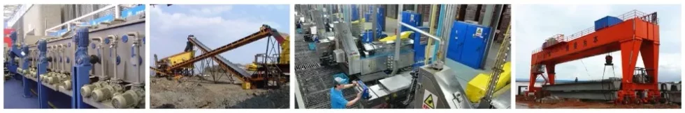
The right angle worm gearbox format of the WPS suits any application where the input and output shafts must be at 90° — and where a compact footprint, quiet operation, and inherent braking at higher ratios are commercially important. Key industries in the Australian market include:
Plastics & Extrusion
Feed screw drives and extruder barrel conveyors operate at 8–25 rpm with sustained torque — exactly the envelope where the WPS’s 30:1 to 50:1 ratio range delivers the best energy-per-torque value at industrial scale.
Beverage & Food Manufacturing
Bottling conveyor chains, can-line turntable drives, and filling station index tables rely on the WPS’s low vibration and smooth speed delivery to maintain product registration without rejects.
Mining Support Equipment
Underground ventilation damper drives, ore-bin discharge gates, and surface stockpile conveyor drives use the WPS in sizes 80–200 where the environmental dust loading makes the sealed cast iron housing a practical necessity.
Lifting & Material Handling
Pallet lifters, dock levellers, and goods hoists routinely specify WPS units at 50:1 or 60:1 ratios where the self-locking geometry prevents descent under gravity without powered braking — a significant safety compliance benefit.
Chemical Industry
Reactor agitators, solvent mixing tanks, and chemical transfer screw conveyors encounter corrosive ambient conditions. The WPS’s cast iron housing receives an external epoxy primer as standard and can be supplied with further chemical-resistant coating on request.
WPS Performance Data: Speed, Torque & Efficiency Reference
The following reference data assists in rapid application screening at 1,450 rpm motor input. All figures represent rated continuous duty values at 20 °C ambient with ISO VG 220 mineral oil lubrication. Apply appropriate service factors before finalising frame selection:
| Size | Ratio | Output Speed (rpm) | Max Torque (N·m) | Approx. Efficiency |
|---|---|---|---|---|
| 40 | 10:1–60:1 | 24–145 | 19–50 | 62–82% |
| 60 | 10:1–60:1 | 24–145 | 60–140 | 62–82% |
| 80 | 10:1–60:1 | 24–145 | 160–380 | 62–82% |
| 100 | 10:1–60:1 | 24–145 | 380–800 | 62–82% |
| 135 | 10:1–60:1 | 24–145 | 900–1,800 | 62–82% |
| 175 | 10:1–60:1 | 24–145 | 1,400–2,745 | 62–82% |
Note: efficiency values apply at 10:1 (highest) and 60:1 (lowest) respectively. Actual values vary with load and lubrication temperature.
Ordering, OEM Customisation & After-Sales Support
Standard WPS configurations across the complete size-ratio matrix are maintained in production stock. For Australian buyers, lead time from confirmed purchase order to dispatch is typically 5–10 business days for standard catalogue combinations. Delivery to Eastern Australia via road freight from the Asian manufacturing base runs approximately 7–14 calendar days from dispatch, depending on the forwarding agent and customs clearance timing.
OEM and batch purchasers (20+ units per order) access preferential pricing with volume commitments. Custom specifications — including special shaft diameters, non-standard ratio combinations, hollow shaft output configurations, and private-label housing markings — are accommodated with a 2–4 week production lead time. All custom units ship with a dimensional verification certificate and a run-test report confirming noise level below the specification threshold at rated speed.
After-sales support includes replacement part availability (worm wheel, seal kits, bearings) for all current production sizes, and technical application support for commissioning issues. Visit the product catalogue for dimensional drawings, or reach the engineering team via the contact page for application-specific selection assistance.