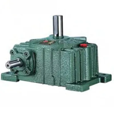
Description
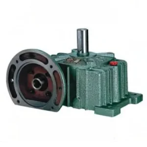
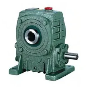
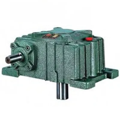
The O & X Series Single Standard Worm Gear Reducer — catalogued as WPO and WPX respectively — represents the dual-output-shaft branch of the WP worm reducer family. Where conventional WP units drive a single load from one output stub, the WPO and WPX housings are machined to present two co-axial output shaft extensions on opposite sides of the gear centre, or in some configurations at 90° to each other. This geometric flexibility solves a class of real engineering problems that single-output reducers cannot address without additional splitter gearboxes or chain-and-sprocket distribution stages. Covering sizes 50 through 250 with the standard 10:1–60:1 ratio range, the O & X series is a compact solution for the industrial worm gearbox market segment where twin-load drive is required within a single sealed housing.
Technical Specifications — O & X Series (WPO / WPX) Worm Reducer
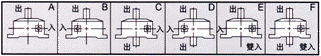
WPO (FCO) — Shaft Configuration
Input shaft at 90° to twin co-axial output shafts. Both output stubs extend from opposite faces of the housing on the same axis.
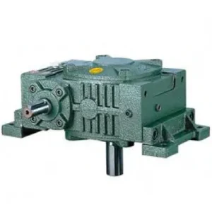
WPX (FCX) — Shaft Configuration
Input shaft co-axial with one output; second output exits at 90°. Useful for offset-axis distribution drives in tight equipment envelopes.
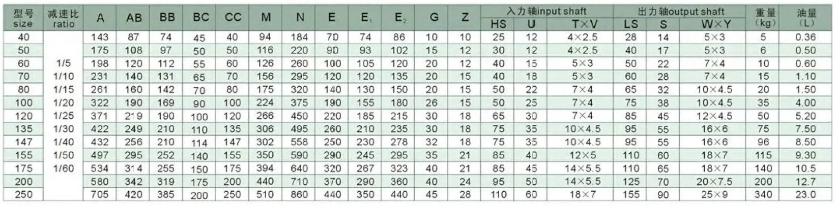
| Size | Ratio | A (mm) | AB (mm) | B (mm) | Output LS (mm) | Output S (mm) | Weight (kg) |
|---|---|---|---|---|---|---|---|
| 50 | 1/10–1/60 | 175 | 105 | 145 | 40 | 17 | 0.5 |
| 60 | 1/10–1/60 | 195 | 120 | 165 | 50 | 22 | 0.6 |
| 70 | 1/10–1/60 | 234 | 140 | 195 | 60 | 28 | 1.1 |
| 80 | 1/10–1/60 | 264 | 160 | 210 | 65 | 32 | 1.44 |
| 100 | 1/10–1/60 | 322 | 190 | 245 | 75 | 38 | 3.0 |
| 120 | 1/10–1/60 | 385 | 230 | 285 | 85 | 45 | 5.1 |
| 135 | 1/10–1/60 | 435 | 260 | 320 | 95 | 55 | 7.2 |
| 155 | 1/10–1/60 | 507 | 302 | 392 | 110 | 60 | 9.0 |
| 175 | 1/10–1/60 | 550 | 325 | 412 | 110 | 65 | 10 |
| 200 | 1/10–1/60 | 590 | 350 | 480 | 125 | 70 | 12 |
| 250 | 1/10–1/60 | 710 | 420 | 560 | 155 | 90 | 22 |
Dual Output Shafts
Ratios 10:1 – 60:1
WPO & WPX Variants
Oil-Bath Lubricated
Right-Angle Drive
Why the O & X Series Solves Problems Single-Output Reducers Cannot
The engineering case for a dual-output worm reducer is straightforward: every time two co-axial loads must be driven at identical speed and phase, inserting an external splitter chain or belt drive introduces an extra failure point, alignment challenge, and ongoing maintenance requirement. The WPO and WPX eliminate that intermediate stage by building the distribution function directly into the sealed reducer housing.
Balanced Load Distribution
Both output shafts draw from the same worm wheel, guaranteeing synchronised rotation with zero phase error between driven loads. In twin-auger food processing lines, this eliminates product bridging caused by differential screw speeds.
Reduced Drivetrain Footprint
Replacing a single-output reducer plus external distribution chain with one WPO or WPX unit typically reduces the drivetrain envelope by 35–50%, a measurable advantage in Australian skid-mounted plant where compact module dimensions affect transport classification.
Sealed Distribution — No External Chain
The oil-bath environment of the WPO/WPX housing means the power split occurs in a clean, lubricated environment. There is no exposed chain to collect grain dust, soil, or process chemicals — a key hygiene advantage in Australian food and grain processing facilities.
Single Lubrication Point
One oil fill, one oil drain, one seal inspection — compared to a reducer-plus-chain arrangement requiring chain lubrication, chain tension adjustment, and sprocket wear monitoring as separate maintenance tasks.
WPX Off-Axis Flexibility
The WPX configuration routes one output at 90° to the other, enabling an L-shaped drive arrangement where two driven axes must occupy a corner layout — common in poultry processing conveyors and automated sorting systems.
Standard WP Gear Set — Proven Core
The internal gear set is identical to the WPA/WPS family, meaning service parts (worm wheels, seals, bearings) are shared across the WP range. Australian maintenance teams with existing WP stock rarely need separate spare-parts holdings for the WPO/WPX.
Housing Architecture and Shaft Arrangement Engineering
Extended Housing Bore Geometry
The WPO housing differs from the WPA at the same nominal size by machining both faces of the output shaft axis to accept shaft extensions and bearing assemblies. This requires the housing casting to carry additional wall thickness on the secondary output face — typically 8–12 mm more than a single-output equivalent — to maintain the bore cylindricity required for the H7 bearing outer race fit under the additional radial load from the second output. The result is a housing that is marginally heavier than the single-output equivalent at the same size but structurally capable of accepting full rated load on both output stubs simultaneously.
Worm Wheel Load Sharing Between Two Outputs
A common misconception in specifying the WPO is assuming each output delivers the full rated torque of the equivalent single-output reducer. This is incorrect: the worm wheel drives both output shafts simultaneously through the shared wheel hub, meaning the total output torque is shared between the two stubs. If the application requires each output shaft to deliver T (Nm), the WPO must be sized for 2T combined output torque at the rated ratio. For uneven loads (one output carrying 60%, the other 40%), the combined torque is still the governing figure for mechanical sizing, but the thermal rating calculation must use the total power input, not the average.
Output Shaft Bearings — Dual Cantilever Consideration
In the WPO, both output shafts are independently supported by tapered roller bearings (sizes 80 and above) or paired deep-groove ball bearings (sizes 50–70). Each shaft extension presents an overhung load from its driven element. Because the two overhung loads act in opposite directions along the same axis, there is a partial cancellation of the resulting bending moment on the wheel hub — a subtle structural advantage over a single heavily loaded output shaft. This means the WPO can, in some loading scenarios, handle higher individual output overhung loads than the catalogue single-output OHL figure would suggest, though the manufacturer’s published values should still be taken as the safe limit without additional structural analysis.
Application Environments Where the WPO & WPX Deliver Real Advantage
The following represent the application archetypes where selecting the O & X series directly eliminates a drivetrain complexity rather than simply substituting one reducer for another:
- 🌾 Twin-Auger Grain Handling Systems
Side-by-side parallel screws in grain cleaners and seed dressers must run at precisely matched speeds to prevent inter-screw packing. A size 100–120 WPO at 30:1–40:1 ratio drives both screws from a single motor through the dual output stubs, eliminating the chain drive synchronisation stage and its associated tensioner maintenance. - 🍇 Winery and Distillery Paddle Agitators
Fermentation tank agitators with two paddle shafts entering from opposite faces of the tank are a natural WPO application. The reducer mounts on the tank top-plate centreline; both paddle shafts receive identical torque and speed. The sealed housing prevents wine vapour or steam condensate from entering the gear mesh. - 🏭 Packaging Machine Infeed & Outfeed Conveyors
Parallel infeed and outfeed belt conveyors flanking a packaging machine must run at matched speed. A size 60–80 WPO at 20:1 ratio driven by a single motor eliminates the independent drive motors and speed-matching VFDs that would otherwise be required, reducing electrical panel complexity and energy cost. - 🚜 PTO-Driven Multi-Section Spreaders
Agricultural spreaders with two rotor shafts benefit from the WPX’s off-axis geometry, where the tractor PTO drives through the main axis and one of the 90° outputs drives a cross-conveyor chain while the other drives the spinner rotor — all from one sealed unit requiring a single PTO shaft connection. - 💧 Irrigation Pump & Dosing System Drives
A WPO at size 80–100 can simultaneously drive a primary irrigation pump through one output and a chemical dosing pump (at proportional speed through different sprocket sizing) through the other — maintaining the correct chemical-to-water ratio without electronic flow control. - 🔄 Poultry Processing Line Transfers
WPX units are used in poultry processing to drive an overhead shackle conveyor (primary output) and a cross-transfer conveyor at 90° (secondary output) from a single motor, maintaining the required bird spacing at both conveyors with a single speed reference.
PTO Shaft Integration and Accessory Components for WPO / WPX
Because the WPO and WPX handle dual-load drive scenarios, the input drive components require careful matching. The following components are typically specified alongside the reducer itself:
Agricultural PTO Shaft Assembly
A telescoping PTO shaft connects tractor 540/1000 rpm output to the WPO/WPX input. Because the dual output means the input is carrying the combined load of both driven shafts, shaft torque rating must account for total gearbox input power — not just one output load.
Torque-Limiting Slip Clutch (Input)
A slip clutch on the input shaft protects the worm gear set when one output shaft jams while the other continues to run — a failure mode unique to dual-output configurations where the full motor torque can be concentrated at a single jammed output.
Output Shaft Couplings (×2)
Both output stubs require independent jaw or disc couplings. Matching coupling stiffness on both outputs avoids differential torsional compliance between the two driven loads — important in precision food portioning where inter-conveyor timing matters.
Dual Torque Arm Bracket
For shaft-mounted WPO configurations (hollow bore variant), a purpose-made dual torque arm bracket anchors the housing against the reaction torques from both output shafts, which act in the same rotational direction and are additive on the housing.
Pressure-Equalising Breather
The larger internal surface area of the WPO housing (two output shaft bore penetrations) increases the number of seal locations where positive housing pressure can cause oil weeping. A breather vent is particularly important in this series for continuous-duty applications.
Cooling Fin Extension Kit
Dual-output configurations impose the full combined load on the single worm gear mesh, increasing heat generation per unit time compared to a single-load application. A clip-on aluminium fin kit extending the effective radiation area is strongly recommended for sizes 120+ at continuous duty.
Choosing Between WPO and WPX: A Decision Framework
The WPO and WPX share identical gear sets and dimensional envelopes at each size. The selection between them is determined entirely by the geometric relationship between the two driven loads in the application:
| Criterion | WPO (FCO) | WPX (FCX) |
|---|---|---|
| Output shaft relationship | Co-axial (180°) | 90° offset |
| Typical application layout | Parallel twin drives | Corner / L-shaped layouts |
| Housing length (along output axis) | Longer | Shorter on secondary axis |
| Bearing load symmetry | Balanced (opposing loads) | Asymmetric (check OHL per stub) |
| Spare parts commonality | Full WP family cross-reference | Full WP family cross-reference |
Sizing and Installation Guidance Specific to Dual-Output Configurations
Torque Derating for Dual-Load Operation
When specifying a WPO or WPX, the rated output torque in the catalogue refers to the combined torque capacity of the worm wheel, distributed across both output shafts. If both shafts are loaded equally, each shaft delivers 50% of the combined rated torque. If one shaft is unloaded (e.g., one driven machine is disengaged), the full rated torque is available at the remaining output shaft — but the thermal load on the gearbox is then equivalent to a single-output unit at that torque level, which is typically the more favourable thermal scenario. Always size based on the peak simultaneous load case: both shafts fully loaded at the maximum duty point.
Mounting Orientation and Oil Level
The WPO housing is symmetric about the output shaft axis, so oil fill level references remain valid with either output shaft uppermost or lowermost. The critical orientation constraint is the input shaft: for shaft-horizontal input with shaft-vertical output, the oil level must be adjusted per the manufacturer’s non-standard-orientation fill specification. With the WPX, the asymmetric housing geometry requires particular care — the correct oil level for the WPX in any non-standard orientation should be confirmed with the supplier before commissioning, as the internal baffle geometry differs from the WPO.
Alignment of Both Output Shafts
In twin-driven applications, both output shafts must be individually aligned to their respective driven loads. A misalignment error on one output introduces a cross-load into the worm wheel hub that is not present in single-output configurations. Dial indicator angular and parallel alignment checks should be performed on both output shaft coupling planes before commissioning. The recommended angular misalignment limit is 0.05°/100 mm shaft length for both outputs simultaneously. For comprehensive support across the complete WP reducer range suited to Australian conditions, the team at worm-gearbox.top can provide application-specific dimensional drawings and selection confirmation. Further guidance on agricultural drivetrain integration is available at agricultural gearbox.