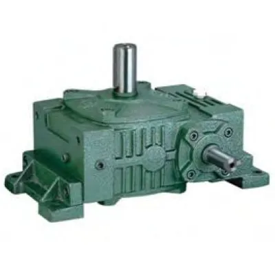
Description
Technical Specifications — WX & WO Series Worm Gear Reducer
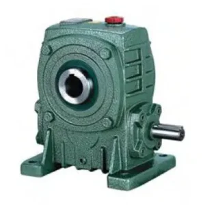
WO Series — Shaft Configuration
Solid through-shaft input (either side) + twin co-axial hollow bore outputs on opposite housing faces. Both bores rotate at identical speed. Suits parallel twin-driven loads in legacy W series machine envelopes.
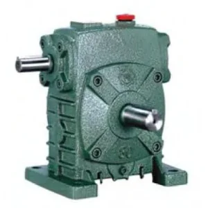
WX Series — Shaft Configuration
Solid through-shaft input (either side) + dual hollow bore outputs at 90° offset. One output co-axial with input axis; second output exits perpendicular. Suits L-shaped twin-drive layouts.
| Size | Ratio | A (mm) | B (mm) | BC (mm) | E1 (mm) | Input HS (mm) | Output LS (mm) | Output S (mm) | Weight (kg) |
|---|---|---|---|---|---|---|---|---|---|
| 40 | 1/10–1/60 | 148 | 123 | 45 | 72 | 25 | 28 | 14 | 4.2 |
| 50 | 1/10–1/60 | 175 | 145 | 50 | 90 | 30 | 40 | 17 | 6.5 |
| 60 | 1/10–1/60 | 195 | 165 | 55 | 102 | 40 | 50 | 22 | 9 |
| 70 | 1/10–1/60 | 234 | 195 | 65 | 120 | 40 | 60 | 28 | 14 |
| 80 | 1/10–1/60 | 264 | 210 | 70 | 140 | 50 | 65 | 32 | 21 |
| 100 | 1/10–1/60 | 322 | 253 | 90 | 165 | 50 | 75 | 38 | 33 |
| 120 | 1/10–1/60 | 385 | 285 | 100 | 195 | 65 | 85 | 45 | 51 |
| 135 | 1/10–1/60 | 435 | 320 | 110 | 230 | 75 | 95 | 55 | 75 |
| 155 | 1/10–1/60 | 494 | 392 | 140 | 250 | 85 | 110 | 65 | 115 |
Ratio 10:1–60:1
Dual Hollow Bore Output
Through-Shaft Input
WO: Co-Axial / WX: 90°
W-Family Dimensional
Three Capabilities in One Sealed Housing
The WX/WO series solves three configuration challenges simultaneously: it drives two loads from a single motor at guaranteed synchronous speed, it shaft-mounts directly onto both driven shafts eliminating all output couplings, and it accepts motor input from either side of the housing. No combination of standard single-output reducers achieves all three without external splitter chains, separate output coupling guards, and a fixed motor position constraint.
Factory-Guaranteed Synchronous Twin Output
Both hollow bore outputs share the same worm wheel — speed ratio between them is exactly 1:1 with zero accumulated phase error. Chain-drive synchronisation between separate reducers accumulates error from chain stretch and sprocket wear; the WX/WO eliminates this entirely.
Motor on Either Side — W Series Heritage
Through-shaft input — both input stubs are active. Motor couples to whichever side suits the machine layout. In legacy W series equipment where motor position was fixed by structural design, this flexibility avoids a machine redesign when replacing the reducer with a dual-output variant.
No Output Couplings — Both Shafts Direct
Both hollow bores seat directly onto their driven shafts — two coupling bodies, two coupling guards, and two alignment procedures are removed from the system simultaneously. In food-grade environments, this eliminates two catch points and two contamination gaps from the machine’s external surface.
Self-Locking at ≥ 30:1 — Both Outputs Hold
The worm mesh self-locking holds both output bores simultaneously on power-off. In twin-auger grain handling systems, both auger shafts are held stationary against full-column grain weight at shutdown — no separate brake required on either shaft.
WX 90° Geometry — L-Layout Without External Bevel
The WX secondary bore exits at 90° to the primary — an internal geometry that avoids an external bevel stage for L-shaped twin-drive arrangements. Agricultural spreader rotors, poultry processing corner transfers, and packaging corner conveyors all use this geometry without additional gearbox stages.
W Series Footprint — Legacy Compatible
The WX/WO housing follows W series external dimensions — A, B, and foot pad configuration match the W series convention. Existing W series machine mounts accommodate the WX/WO without baseplate modification when upgrading from single-output to dual-output drive.
WO vs WX: Choosing the Correct Dual-Output Geometry
| Criterion | WO (Co-Axial) | WX (90° Offset) |
|---|---|---|
| Output bore geometry | 180° — opposite faces | 90° — perpendicular |
| Best application layout | Parallel in-line twin drives | L-shaped corner drives |
| Bore load symmetry | Opposing — partially cancel | Asymmetric — check OHL per bore |
| Internal bevel stage | None | Built-in (2–4% added loss) |
| Typical applications | Twin augers, fermentation paddles, matched conveyors | Spreader rotors, poultry transfers, packaging corners |
The Torque Sharing Rule — Most Common Specification Error
Both output bores share the same worm wheel. The rated output torque is the combined figure across both bores — not the per-bore figure. If each driven shaft requires T (Nm), the WX/WO must be sized for 2T combined output torque at the selected ratio. Applying the rated torque figure to each bore independently is the most common sizing error with dual-output units and leads to premature worm wheel failure within one or two seasons.
Correct Sizing Procedure
- Calculate T1 and T2 (Nm) for each driven load — apply shock service factor per shaft independently
- Sum: T_combined = T1 + T2 — this is the figure to compare against the WX/WO rated output torque
- Select WX/WO size where rated output torque ≥ T_combined at the selected ratio
- Verify thermal rating at T_combined / (ratio × η) input power in actual ambient temperature
- Confirm total torque sizing; a 60%/40% uneven load split is acceptable as long as T1 + T2 ≤ rated combined
Application Environments — Where WX/WO Eliminates Multi-Unit Complexity
- 🌾 Twin-Auger Grain and Seed Handling (WO)
WO size 100–120 at 30:1–40:1 drives matched grain auger screws from a single motor through co-axial bores. Both screws run at exactly matched speed — eliminating grain bridging from differential auger speed. Through-shaft input accommodates motor positioning to clear the hopper structure on either side. - 🚜 Agricultural Twin-Rotor Spreaders (WX)
WX size 80–100 drives the spreader rotor and cross-conveyor chain from a single input. The 90° output geometry suits the spreader layout without an external bevel stage. Through-shaft input allows the PTO shaft to connect on either side of the machine chassis. For PTO shaft sizing guidance, refer to our agricultural PTO shaft technical resources. - 🍇 Fermentation Tank Dual-Paddle Agitators (WO)
WO top-mounted on a fermentation tank lid drives two paddle shafts entering from opposite tank faces. Both paddles receive identical torque and speed. Through-shaft input allows the motor to be positioned clear of the tank top pipework on either side without changing the reducer orientation. - 📦 Packaging Machine Infeed/Outfeed Pair (WO)
WO size 60–80 at 20:1 drives matched infeed and outfeed belt conveyors from a single motor. Eliminates two independent motor-reducer pairs and their individual VFDs — motor positioning flexibility accommodates the constrained side of the machine frame. - 🏭 Poultry Processing Line Corner Transfers (WX)
WX size 60–80 drives an overhead shackle conveyor (primary bore) and a 90°-direction cross-transfer conveyor (secondary bore) from a single washdown-rated motor. Through-shaft input allows the motor to be positioned on whichever side clears the process line infrastructure.
Input Options and Drive Accessories
Motor + Jaw Coupling (Standard)
Couple any IEC or NEMA motor to either input stub via a jaw coupling. Cap the unused stub with the supplied blanking cap and lip seal. The total input power must cover the combined load of both driven shafts divided by the worm mesh efficiency at the selected ratio.
PTO Shaft + Slip Clutch (Agricultural)
PTO shaft with yoke coupling to input stub. Fit a friction slip clutch rated at 1.5× combined input torque — critical because a jam on one output shaft can concentrate full motor torque at the jammed bore while the other continues running.
Dual Shrink Discs (Shock Loads)
Both output bores require locking elements. For shock-load applications, specify shrink discs for both bores — uniform radial clamping prevents the progressive set screw loosening that repeated shock torques cause in either bore independently.
Dual Torque Arms (Shaft-Mount Config)
In shaft-mount configuration, both bore output shafts react torque in the same rotational direction — their torque arm loads are additive on the housing. A dual-bushed torque arm must carry the combined reaction torque of both output shafts plus the motor + reducer weight moment.
Pressure-Equalising Breather
The WX/WO has three shaft penetrations (one input each side + two output bores). Positive housing pressure from continuous duty causes oil weeping at the bore seals. A breather vent at the filler port prevents this — particularly important in the WX where the 90° bore geometry creates additional dynamic oil splash patterns.
Unused Input Blanking Cap
The unused input stub must be capped and sealed at all times. The WX/WO has four potential contamination entry points (two input stubs, two output bore ends) — the blanking cap and both bore end seals must be inspected at each scheduled oil change and replaced at the first sign of lip wear or hardening.
Maintenance Schedule — WX/WO Four-Penetration Sealing Protocol
| Interval | Task | WX/WO-Specific Note |
|---|---|---|
| First 500 hours | Oil flush; all four penetration seals + blanking cap | Inspect both output bore end faces for early fretting signs — rust-brown powder at bore end indicates inadequate locking force |
| Every 2,500 hours | Oil change; inspect all seals; both shrink disc re-torque | Replace blanking cap lip seal proactively — in dusty environments, do not wait for visible contamination signs |
| Every 5,000 hours | Remove both bores from shafts; full contact zone inspection | WX: check both bore zones individually — the 90° bore experiences different dynamic loads from the co-axial bore and may wear at different rates |
| If one bore jams | Full worm wheel inspection before return to service | Full motor torque concentrated at jammed bore can damage worm wheel even if motor trips promptly — inspect regardless of apparent outer condition |

For WX/WO bore sizing, torque arm design assistance, and application selection support for Australian plant, the engineering team at our worm gearbox technical portal can provide combined torque calculations and dimensional drawings. For agricultural PTO integration guidance, contact us via the technical enquiry page with your driven shaft diameters and combined load torque.