Description
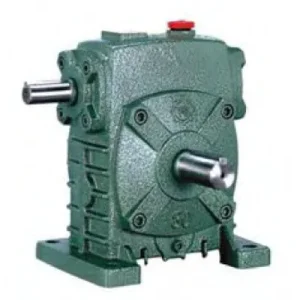
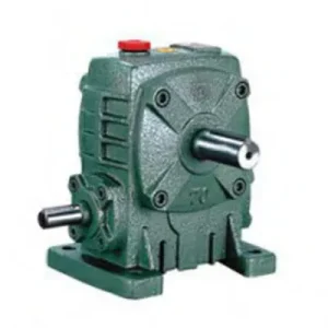
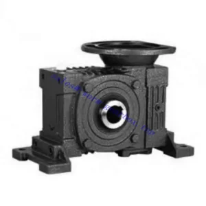
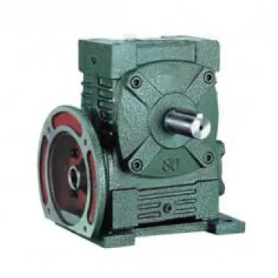
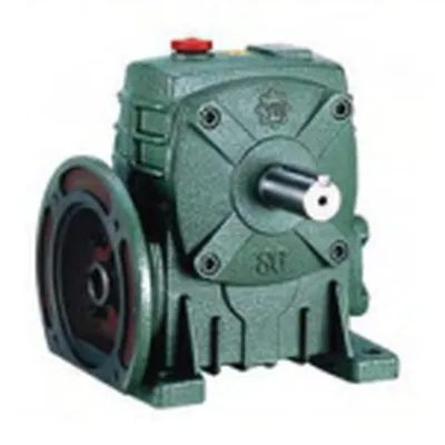
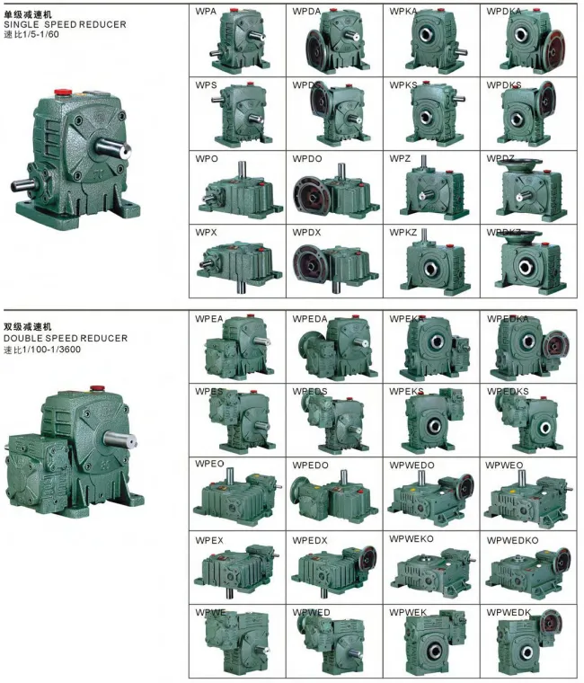
The DA Series Single Standard Worm Gear Reducer — designated WPDA — occupies a technically distinct position within the WP family by incorporating a motor-mounting flange directly into the reducer housing. While the WPA, WPS, WPO, and WPX are all coupled to their motors through separate flexible couplings and motor bases, the WPDA presents an IEC-standard input flange face machined concentrically with the worm shaft axis. This allows an IEC-frame electric motor to bolt directly onto the reducer without any intermediate coupling housing, baseplate, or alignment procedure — effectively forming an integrated motorised worm gear drive unit. Covering sizes 50 through 155, with power inputs from 0.18 kW to 5.5 kW and gear ratios from 10:1 to 60:1, the WPDA is the specification of choice when compact motor-reducer integration is the primary engineering requirement.
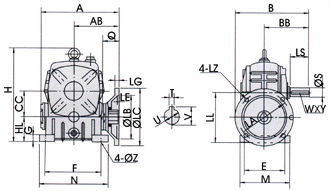
Technical Specifications — DA Series WPDA Worm Gear Drive
| Size | Power (kW) | Ratio | A (mm) | B (mm) | H (mm) | Flange LA (mm) | Output LS (mm) | Weight (kg) |
|---|---|---|---|---|---|---|---|---|
| 50 | 0.18 | 1/10–1/60 | 165 | 175 | 180 | 115 | 40 | 7 |
| 60 | 0.37 | 1/10–1/60 | 185 | 190 | 205 | 130 | 50 | 11 |
| 70 | 0.37 / 0.75 | 1/10–1/60 | 209 | 210 / 230 | 235 | 130 | 60 | 15 |
| 80 | 0.75 / 1.5 | 1/10–1/60 | 242 | 240 | 265 | 165 | 65 | 23 |
| 100 | 1.5 | 1/10–1/60 | 310 | 255 | 363 | 165 | 75 | 38 |
| 120 | 2.2 / 3.0 | 1/10–1/60 | 361 | 310 | 424 | 215 | 85 | 65 |
| 135 | 3.0 / 4.0 | 1/10–1/60 | 412 | 335 | 481 | 215 | 95 | 84 |
| 155 | 5.5 | 1/10–1/60 | 442 | 402 | 536 | 265 | 110 | 120 |
Input Flange Dimensions (LZ = Flange Register / M-bolt thread)
| Size | LZ (Flange register mm) | Bolt circle LB (mm) | Bolt M-size | Bolt count |
|---|---|---|---|---|
| 50 | 140 | 95 | M8 | 4 |
| 60 | 160 | 110 | M8 | 4 |
| 70 | 160 / 200 | 110 / 130 | M8 / M10 | 4 |
| 80 | 200 | 130 | M10 | 4 |
| 100 | 200 | 130 | M10 | 4 |
| 120 | 250 | 180 | M12 | 4 |
| 135 | 250 | 180 | M12 | 4 |
| 155 | 300 | 230 | M12 | 4 |
0.18 – 5.5 kW
Sizes 50 – 155
IEC B5 Flange Input
10:1 – 60:1 Ratios
Foot + Flange Mount
The WPDA Engineering Advantage: Why Direct Motor Mounting Matters
The conventional approach to assembling a motor-reducer combination involves a motor base, a flexible coupling, and a separate coupling guard — three additional components, each requiring individual alignment, fastening, and periodic inspection. The WPDA eliminates all three by integrating the motor attachment function into the reducer casting itself. This creates a series of measurable engineering benefits:
Factory-Precision Alignment
The motor shaft and worm shaft are concentric to within 0.05 mm TIR because both are referenced to the same machined flange bore. This eliminates the angular and parallel misalignment that is inherent in separately coupled motor-reducer assemblies, even when carefully aligned.
Elimination of Coupling Failures
Flexible coupling element fatigue and jaw spider degradation are among the most frequent drivetrain failure modes in Australian food and packaging plant. The WPDA eliminates the coupling entirely — the motor shaft inserts directly into the worm shaft input bore, secured by a keyed connection only.
Reduced Installed Footprint
With the motor bolting directly onto the reducer face, the combined unit occupies 20–35% less axial length than a separately mounted motor-coupling-reducer arrangement. This is particularly valuable in retrofitting drives into confined spaces in older Australian processing facilities.
Faster Site Assembly
Commissioning a WPDA unit involves bolting the motor to the flange, mounting the reducer to its baseplate, and wiring the motor — there is no coupling alignment, no dial indicator, no feeler gauge. In high-volume OEM production, this simplification can reduce assembly labour by 45–60 minutes per unit.
Motor Interchangeability
The IEC B5 flange interface is an industry standard — any IEC-dimensioned motor of the correct frame size will mate with the WPDA flange. Motor replacement for repair or power upgrade requires no machining, no coupling re-boring, and no baseplate modification.
No Exposed Coupling Guard Required
Australian WHS regulations require guarding of all rotating couplings. The WPDA’s motor-direct arrangement has no external rotating element between motor and reducer — the only unguarded rotating part is the output shaft, which requires guarding regardless of reducer type.
Input Flange Engineering and IEC Motor Frame Compatibility
Flange Register and Motor Frame Matching
The input flange bore (LZ dimension) of each WPDA size is machined to accept the flange register (D-dimension) of a specific IEC motor frame. The critical matching criteria are the flange register diameter (LZ / IEC D), the bolt circle diameter (LB), bolt thread size, and the motor shaft diameter (Q dimension of the WPDA input hole). Before ordering a WPDA unit, confirm the IEC frame designation of the intended motor — typically stated on the motor nameplate as “IEC 71”, “IEC 80”, “IEC 90” and so on — and cross-reference with the WPDA flange dimension table to confirm compatibility. Adaptor plates are available for non-standard motor frames.
Input Hole and Motor Shaft Fit
The WPDA input hole (Q and U dimensions) receives the motor shaft extension directly. The standard fit is H7/j6 — a close running-clearance fit that centres the motor shaft in the worm shaft bore while still allowing manual disassembly without pressing equipment. A parallel key, supplied with the unit, transmits the motor torque. It is important to confirm that the motor shaft length does not exceed the WPDA input bore depth (T×V dimension); an overlong motor shaft that bottoms out in the bore will prevent the motor flange from seating flat against the reducer flange face, introducing angular misalignment that defeats the purpose of the direct-mount arrangement.
Foot Mounting Integration
Despite its integrated motor flange, the WPDA retains the standard WP foot-mounting pad arrangement on the underside of the housing. This means the complete motor-reducer assembly can be foot-mounted as a single unit to a baseplate or structural steel frame, with all four mounting pads taking the combined weight and dynamic loads of both motor and reducer. The foot pad dimensions follow the standard WP dimensional series, making the WPDA a direct drop-in replacement for WPA or WPS units where motor-direct mounting is being retrofitted.
Where the WPDA Delivers Maximum Value in Australian Industry
The WPDA’s direct motor integration makes it particularly well-suited to application environments where assembly simplicity, compact envelope, or rapid motor replacement are prioritised alongside the torque-reduction performance of the worm gear set:
- 📦 OEM Packaging Machinery
Size 50–70 WPDA units at 20:1–40:1 ratio are the dominant choice for indexing mechanisms, lid applicators, and labelling heads in Australian-built packaging machines. The compact unit is self-contained and pre-aligned — OEM assembly staff do not require mechanical skills beyond bolting the motor and mounting the unit. - 🏪 Retail Display and Automated Gate Systems
Automated gate actuators and rotating display platforms in retail and security applications use size 50–60 WPDA units at 40:1–60:1 ratios, where the self-locking characteristic at high ratios provides position-holding without a brake, and the compact direct-drive format suits the concealed drive enclosures common in these installations. - 🌾 Agricultural Equipment OEM Builds
Small-scale agricultural implements — seed metering units, chemical injection pumps, and variable-rate applicator drives — increasingly use the WPDA where electric motor drive is preferred over PTO shaft integration. The unit’s IEC flange suits standard TEFC motors readily available from Australian electrical wholesalers, avoiding long lead times for specialist agricultural motors. - 🏗️ Material Handling Turntables and Positioners
Pallet turntables, welding positioners, and part-rotation fixtures in Australian manufacturing plants use size 80–120 WPDA units at 20:1–60:1 ratios. The worm’s self-locking holds the table position under load without power, and the direct-mount format simplifies the control panel wiring by eliminating the coupling guard interlock that would otherwise be required. - 💧 Wastewater and Water Treatment Plant Auxiliaries
Slow-speed mixer drives, sludge scrapers, and chemical dosing screw drives in water treatment plants use size 100–135 WPDA units, where the IP55 sealing of the combined motor-reducer unit matches the wet-area requirements and the integrated assembly simplifies the plant’s stainless structural support frameworks. - 🔬 Pharmaceutical and Laboratory Equipment
Mixing and dispensing equipment in pharmaceutical manufacturing uses size 50–80 WPDA units where stainless output shaft extensions and food-grade lubricant options are specified. The sealed housing and no-exposed-coupling format aligns with GMP facility requirements for cleanroom-adjacent equipment rooms.
Drive Components, PTO Integration, and WPDA Accessories
While the WPDA is most commonly motor-flange mounted, it is also used in PTO-shaft-driven configurations for smaller agricultural implements where a direct flange-to-implement-gearbox interface is required. The following components are typically associated with a complete WPDA drivetrain:
IEC Motor (TEFC, B5 Flange)
The WPDA is designed for direct-mount IEC B5 flange motors. Standard 4-pole TEFC motors at 1,450 rpm suit most applications; 6-pole (960 rpm) motors reduce input speed for applications with tight output speed requirements at moderate ratios.
Agricultural PTO Shaft (Flange Input Variant)
For PTO-driven WPDA configurations, a PTO shaft with a flange-end adaptor matches the WPDA’s input flange bore, providing the 540/1000 rpm tractor output connection without modifying the standard WPDA housing.
Output Shaft Coupling and Guard
Although the WPDA eliminates the input coupling, the output shaft still requires a coupling and guard for connection to the driven load. A jaw coupling with a close-fitting polycarbonate guard is the standard solution for WHS-compliant installation.
Motor Adaptor Plate (Non-Standard Frames)
For motors with non-IEC flanges (NEMA C-face, or metric motor frames outside the standard IEC series), a machined adaptor plate bridges between the motor’s own flange and the WPDA’s input face. These are available as custom components with 2–3 week lead time.
Thermal Overload Relay (Motor Protection)
Because the motor and reducer form a single thermal unit, motor winding overtemperature caused by worm gear overloading must be managed by a correctly set thermal overload relay in the motor starter — set to 1.0× motor FLA, not the common practice of setting to 1.1× or 1.15× which can mask worm gear overload conditions.
VFD (Variable Frequency Drive)
The WPDA is compatible with VFD control. For variable-speed operation below 25 Hz (900 rpm input), specify a force-ventilated motor (separate cooling fan) to maintain motor thermal rating at reduced speeds. This is the most common add-on specification for WPDA units in Australian food processing automation.
Step-by-Step WPDA Motor Mounting and Commissioning Process
Verify Motor Frame and Shaft Compatibility
Confirm the motor’s IEC frame code, shaft diameter (typically D-end), shaft length (E-dimension), flange register (D-dimension), and bolt circle (M-dimension) all match the WPDA input flange specification for the selected size. Check that the motor shaft length does not exceed the WPDA input bore depth (T×V dimension).
Fit the Key and Insert Motor Shaft
Lightly lubricate the motor shaft extension with clean gear oil (not grease — grease will trap air and prevent full shaft insertion). Align the motor keyway with the WPDA input bore keyway. Slide the motor shaft into the WPDA bore; it should enter smoothly under hand force. Do not hammer — if resistance is felt, verify bore and shaft diameters against the specification before proceeding.
Bolt Motor Flange to WPDA Flange
Seat the motor flange face against the WPDA input flange face. Insert flange bolts and tighten in a diagonal sequence to the specified torque: M8 = 22 Nm, M10 = 44 Nm, M12 = 77 Nm. Do not overtighten — the flange register centring, not bolt friction, carries the radial load from motor shaft weight.
Mount the Combined Unit and Connect Output
Mount the WPDA foot pads to the prepared baseplate. Fit the output shaft coupling, guard, and driven load connection. The combined motor-reducer weight must be supported at the foot pads only — do not support the motor separately, as this introduces a secondary reaction moment into the WPDA housing.
Commission: Check Oil Level and Run-In
WPDA units are shipped pre-filled with ISO VG 220 mineral gear oil. Verify the oil level at the sight glass before first start. Run unloaded for 30 minutes, then at 50% load for 2 hours, monitoring housing temperature. Normal operating temperature should stabilise below 70°C above ambient at rated load. Drain and replace oil after 500 hours to flush run-in bronze particles.
Maintenance Specifics for the WPDA Motor-Direct Configuration
The WPDA introduces one maintenance consideration not present in separately coupled configurations: motor replacement. When a motor fails on a WPDA unit, the replacement motor must be the same IEC frame size as the original. A different frame motor requires either a different WPDA size or a custom adaptor plate — a mismatch discovered at 3 a.m. during a production breakdown is a costly delay.
| Interval / Trigger | Task | Notes |
|---|---|---|
| First 500 hours | Oil drain and refill (run-in flush) | Critical — bronze wheel run-in particles accumulate in first 500 hrs |
| Every 2,500 hours | Full oil change; inspect output shaft seal | ISO VG 220; check for seal weeping around output stub |
| Every 5,000 hours | Motor flange bolt torque check | Vibration can loosen flange bolts over time — re-torque to spec |
| Motor replacement | Verify replacement frame code before ordering | Keep a record of the original motor frame on the plant maintenance schedule |
| At any seal replacement | Inspect output bearing radial play | Radial play >0.1 mm indicates bearing wear; replace before returning to service |
For specification support across the full DA series range and access to the complete worm gearbox product portfolio for Australian applications, our technical team provides selection calculations, IEC motor frame cross-referencing, and CAD dimensional drawings. To discuss your project requirement, visit the contact page with your motor specification and application data sheet.