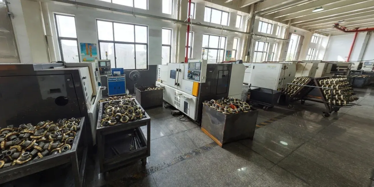
Description
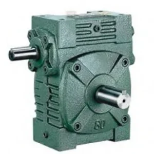
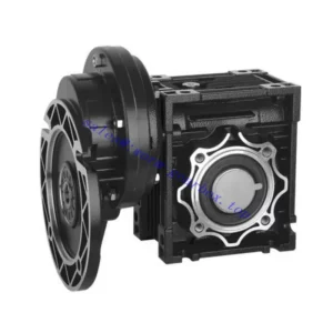
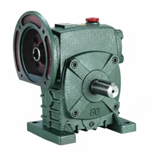
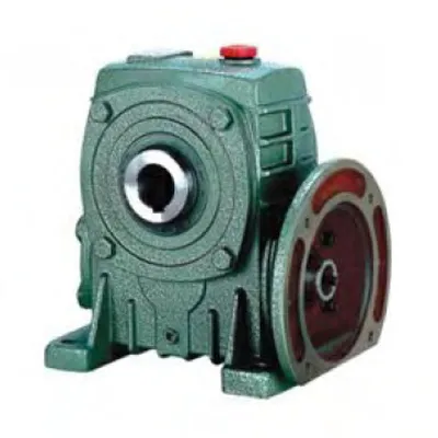
The DKA Series Single Standard Worm Gear Reducer — designated WPDKA — is the most integration-dense unit in the WP family. It is the only configuration that removes couplings from both ends of the drivetrain simultaneously: the IEC B5 motor flange eliminates the input coupling, and the hollow bore output eliminates the output coupling. The motor bolts directly onto the input face; the driven shaft slides directly into the output bore. The result is a compact worm gearbox assembly with two fewer rotating connection points, two fewer alignment procedures, and two fewer coupling guards than a conventional motor–reducer–coupling–shaft arrangement. For Australian OEM machine builders and plant engineers retrofitting drives into confined layouts, this matters directly in assembly time, installed footprint, and ongoing maintenance programme. Covering sizes 50 through 175 with input powers from 0.18 kW to 7.5 kW and standard ratios of 10:1 to 60:1, the WPDKA addresses the application space where the WPDA’s solid output shaft would need a coupling and the WPKA’s separate motor mounting would need a base — and resolves both at once.
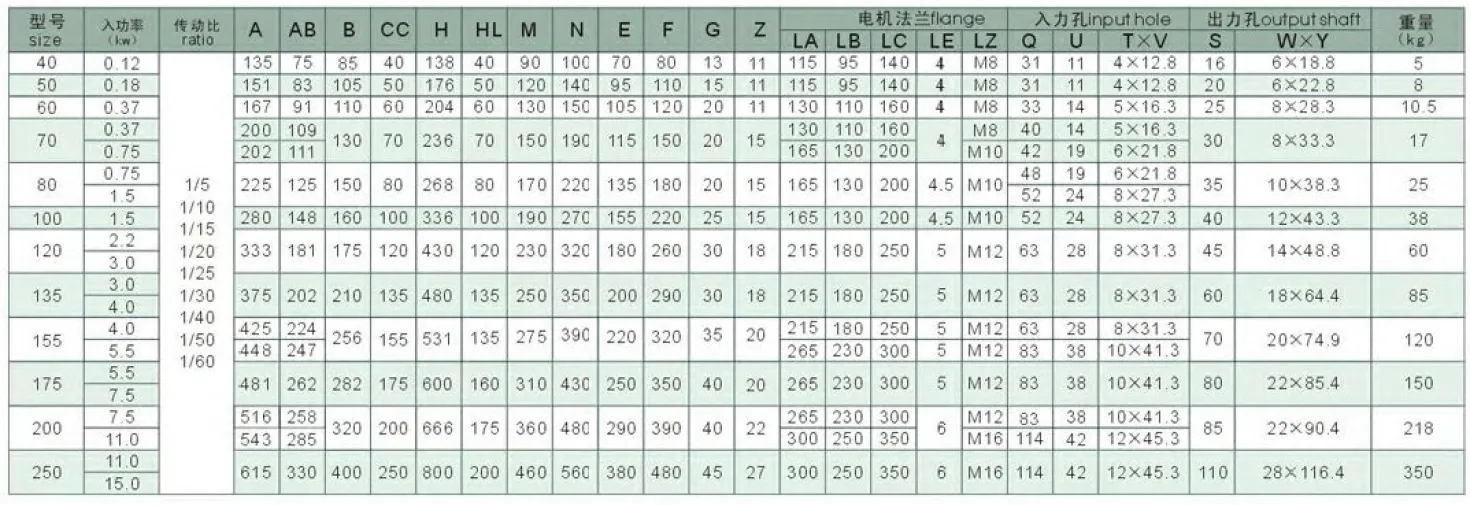
Technical Specifications — DKA Series (WPDKA) Worm Gear Reducer
| Size | Power (kW) | Ratio | A (mm) | B (mm) | H (mm) | HL (mm) | Flange LA (mm) | Output Bore S (mm) | Weight (kg) |
|---|---|---|---|---|---|---|---|---|---|
| 50 | 0.18 | 1/10–1/60 | 155 | 107 | 180 | 50 | 115 | Ø20 | 8 |
| 60 | 0.37 | 1/10–1/60 | 170 | 117 | 210 | 60 | 130 | Ø25 | 10.5 |
| 70 | 0.37 / 0.75 | 1/10–1/60 | 206 | 131 | 243 | 70 | 130 | Ø30 | 17 |
| 80 | 0.75 / 1.5 | 1/10–1/60 | 232 | 144 | 273 | 80 | 165 | Ø35 | 26 |
| 100 | 1.5 | 1/10–1/60 | 266 | 175 | 340 | 100 | 165 | Ø40 | 38 |
| 120 | 2.2 / 3.0 | 1/10–1/60 | 340 | 200 | 405 | 120 | 215 | Ø45 | 60 |
| 135 | 3.0 / 4.0 | 1/10–1/60 | 375 | 212 | 455 | 135 | 215 | Ø60 | 85 |
| 155 | 5.5 | 1/10–1/60 | 442 | 312 | 490 | 135 | 265 | Ø70 | 120 |
| 175 | 7.5 | 1/10–1/60 | 465 | 334 | 565 | 160 | 265 | Ø80 | 150 |
Input Flange — IEC B5 Interface
| Size | LZ (mm) | LB (mm) | Bolt | Input Q (mm) |
|---|---|---|---|---|
| 50 | 140 | 95 | M8 | 25 |
| 60 | 160 | 110 | M8 | 35 |
| 70 | 160/200 | 110/130 | M8/M10 | 35/45 |
| 80 | 200 | 130 | M10 | 45/55 |
| 100 | 200 | 130 | M10 | 55 |
| 120 | 250 | 180 | M12 | 65 |
| 135 | 250 | 180 | M12 | 65 |
| 155 | 300 | 230 | M12 | 85 |
| 175 | 300 | 230 | M12 | 85 |
Output Key Dimensions
| Size | Key W×Y (mm) |
|---|---|
| 50 | 6×22.8 |
| 60 | 8×28.3 |
| 70 | 8×33.3 |
| 80 | 10×38.3 |
| 100 | 12×43.3 |
| 120 | 14×48.8 |
| 135 | 18×64.4 |
| 155 | 20×74.9 |
| 175 | 22×85.4 |
IEC B5 Flange Input
Hollow Bore Output Ø20–80mm
0.18 – 7.5 kW
Zero-Coupling Drivetrain
Foot + Flange Mount
Zero Couplings, Both Ends — The Core Engineering Case for the WPDKA
Every coupling in a drivetrain is a maintenance item, an alignment target, a WHS guarding requirement, and a failure mechanism. The WPDKA removes them from both ends of the reducer simultaneously. On the input side, the IEC B5 flange provides factory-precision motor concentricity. On the output side, the hollow bore seats directly onto the driven shaft. The driven shaft becomes the structural reference for the entire motor–reducer assembly — and every element between motor shaft and driven shaft exists inside the single sealed housing.
Input Coupling Eliminated
The motor shaft inserts directly into the IEC B5 flange bore. No jaw coupling, no flexible element to degrade, no spider to replace, no coupling guard to fit — and no angular misalignment between motor and worm shafts because both are concentric to within 0.05 mm TIR in the same machined bore.
Output Coupling Eliminated
The driven shaft slides into the hollow bore output and is retained by a DIN 6885 key and a locking element. No output coupling body, no coupling guard, and no parallel alignment procedure — the driven shaft is the mounting reference. The output connection is inside the sealed housing, protected from contamination and moisture.
Fastest Assembly in the WP Family
Installation reduces to three steps: bolt motor to flange, slide unit onto driven shaft, fit torque arm. No dial indicator, no feeler gauge, no coupling bore grinding, no coupling guard fabrication. For high-volume OEM production, this simplification can reduce per-unit assembly labour by 60–90 minutes versus a conventional motor–coupling–reducer–coupling arrangement.
Minimum Axial and Lateral Footprint
With no coupling bodies at either end, the WPDKA is the most axially compact motor-reducer-shaft assembly achievable in the WP family. Motor face bolts directly to flange face; output bore seats at the housing face. Total axial length from motor mounting face to housing face is the reducer A dimension only — nothing more.
Self-Locking Transmitted Directly to Shaft
At ratios of 30:1 and above, the worm mesh holds the output bore stationary on power-off with no back-driving — and this holding torque acts directly on the driven shaft through the bore connection, without the slip risk that coupling fretting can introduce in loaded solid-shaft self-locking arrangements under sustained static loading.
Motor Interchangeability — IEC Standard
Any IEC B5 motor of the correct frame bolts directly to the WPDKA flange — no re-boring, no new coupling, no baseplate modification. Motor replacement in the field requires only an appropriate IEC frame motor from any Australian electrical supplier, correctly matched to the WPDKA flange table at the selected size.
Where the WPDKA Sits in the WP Family — Choosing the Right Variant
Three WP configurations share the WPA frame geometry, and selecting correctly between them avoids over-specification cost and under-specification failure risk:
| Feature | WPKA | WPDA | WPDKA |
|---|---|---|---|
| Input type | Solid shaft + coupling | IEC B5 flange | IEC B5 flange |
| Output type | Hollow bore | Solid shaft + coupling | Hollow bore |
| Input couplings | Required | None | None ✓ |
| Output couplings | None | Required | None ✓ |
| Shaft-mount capable | ✓ | ✗ | ✓ |
| Motor-direct mount | ✗ | ✓ | ✓ |
| Output bearing class | WPA-class (ball) | WPA-class (ball) | WPA-class (ball) |
| Best application | Shaft-mount, separate motor | Motor-direct, solid shaft load | Motor-direct + shaft-mount |
Specification rule: When your application needs both motor-direct input and shaft-mount output, the WPDKA is the only WP-family unit that delivers both without custom modification. If only one of these is needed, the WPDA or WPKA is more economical.
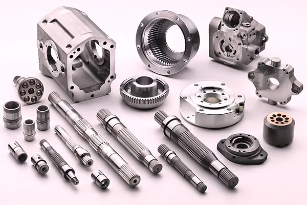
Housing Engineering: Machining Three Precision Features in One Casting
Flange Face, Bore, and Foot — Single-Setup Machining
The WPDKA housing carries three precision-machined functional surfaces that must maintain defined geometric relationships to each other: the IEC B5 input flange face and register bore (co-axial with the worm shaft), the hollow output bore (co-axial with the worm wheel axis, perpendicular to the worm shaft), and the foot mounting pads (parallel to the output bore axis). All three are finished in a controlled machining sequence from a single datum setup — this is what guarantees that the motor axis, worm shaft axis, and worm wheel bore axis maintain their designed angular relationships regardless of housing casting variation. If any two of these faces were machined in separate setups with independent datums, the angular tolerances would stack and the claimed concentricity would be unachievable in production.
Bore Depth and Output Key Engagement
The WPDKA uses the WPA/WPKA-class HL (bore depth) dimension, which is shorter than the WPS/WPKS-class depth at each size number. At size 100, the WPDKA HL is 100 mm versus 250 mm in the WPKS. This is the key constraint that determines the WPDKA’s appropriate application envelope: the shorter bore depth means lower key face engagement length, which translates to lower permissible shock torque at the bore connection. The WPDKA is rated for smooth-to-moderate shock loads (service factor 1.0–1.5); for heavy shock applications (grain stone strikes, conveyor jam events, mining belt slippage), the WPKDS — which combines WPKS bore depth with WPDS motor flange — is the correct specification.
Worm Gear Set and Lubrication
The internal worm gear set follows the standard WPA family specification: case-hardened alloy steel worm shaft ground to Ra ≤ 0.8 µm, phosphor-bronze centrifugally cast worm wheel, oil-bath lubrication with ISO VG 220 mineral gear oil pre-filled. The worm shaft input bore (Q dimension in the flange table) accepts the motor shaft directly; the shaft-bore fit is H7/j6, allowing hand assembly without pressing equipment and maintaining concentricity within 0.02–0.025 mm radial clearance. Input bore depth (T×V dimension) must exceed the motor shaft extension length — verify this before ordering a motor to prevent the motor shaft bottoming out and preventing correct flange face seating.
Application Environments Where the WPDKA’s Dual Integration Pays Off
The WPDKA is not justified by novelty — it earns its place in applications where the combination of motor-direct input and shaft-mount output resolves a specific layout, maintenance, or contamination constraint that neither the WPDA nor the WPKA can address alone:
- 📦 OEM Packaging Machine Conveyor and Metering Drives
Packaging machine builders in Australia use WPDKA size 50–70 at 20:1–40:1 for belt conveyor head drives and product metering shafts where the machine frame is the structural reference. The motor flanges directly to the reducer; the reducer bore-mounts on the conveyor shaft. Zero external drive components are visible outside the machine frame — a key hygiene and visual design requirement for food-grade packaging equipment built to Australian standard AS 4674. - 🏭 Automated Gate and Shutter Actuator Drives
Industrial automated gate systems and roller shutter drives use WPDKA size 60–80 at 40:1–60:1 directly on the gate shaft or drum shaft. The motor flanges to the reducer; the reducer bore-mounts on the drum. The worm self-locking at these ratios holds the gate position on power failure — meeting the AS 1170 structural requirement for automated barrier systems — and the absence of any external coupling removes the primary failure mode in outdoor gate drive enclosures exposed to Australian dust and moisture conditions. - 🌾 Agricultural Implement Electric Drive Conversion
Farmers upgrading tractor PTO-driven implements to electric motor drives use WPDKA size 80–120 to reduce the implement shaft to the required output speed while mounting the motor directly to the reducer flange. The absence of a PTO shaft on the input and the bore-mount output onto the existing implement shaft means the conversion requires minimal structural modification to the original implement frame. For electric drive conversions from PTO shaft power, the WPDKA eliminates the PTO shaft and slip clutch, replacing them with a compact sealed unit. - 💧 Water Treatment and Irrigation Mechanism Drives
Irrigation channel gate actuators and water treatment paddle mixers use WPDKA size 100–135 where the mechanism shaft is the mounting reference. The enclosed sealed housing with motor bolted directly to the flange face presents no external coupling gaps for water ingress — important in Australian irrigation infrastructure where seasonal flooding contacts the drive assembly. The worm self-locking holds gate positions and paddle positions on power-off without any additional locking mechanism. - 🔄 Carousel and Display Turntable Drives
Retail display turntables, exhibition carousels, and stage machinery rotation drives use WPDKA size 50–70 at 40:1–60:1 on the vertical centre shaft. The motor sits above the housing and flanges directly to it; the housing bore-mounts on the shaft. The self-locking holds the turntable stationary when the motor is de-energised — no separate brake required — and the fully enclosed assembly with no external couplings suits the aesthetic requirements of public-facing display environments. - 🔬 Pharmaceutical and Food Processing Equipment
Mixing and dispensing equipment in pharmaceutical manufacturing uses WPDKA size 60–100 where GMP facility requirements limit exposed mechanical components. The fully enclosed motor-flange-reducer-bore-shaft assembly presents no catch points, no coupling gaps, and no grease nipples outside the sealed housing — meeting the cleanroom-adjacent equipment room requirements specified under TGA guidelines for pharmaceutical manufacturing facilities in Australia.

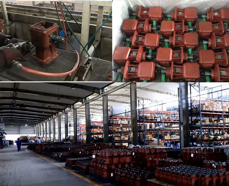
Drive Components and Accessories for a Complete WPDKA Installation
The WPDKA’s coupling-free design reduces the accessory list significantly compared to conventional reducer configurations, but the remaining components — torque arm, locking element, motor — are more critical per unit than in a coupled arrangement because they carry loads that couplings would normally buffer:
IEC B5 Motor (TEFC or Force-Ventilated)
Standard 4-pole TEFC at 1,450 rpm for most applications. For VFD operation below 25 Hz, specify a force-ventilated (IC416) motor to maintain thermal rating. Confirm motor shaft length ≤ WPDKA input bore depth T×V before ordering — a shaft that bottoms out prevents correct flange seating and introduces angular misalignment.
PTO Shaft — Flange Adaptor for Agricultural Use
Where a tractor PTO drives the WPDKA rather than an electric motor, a PTO shaft with flange-end adaptor engages the WPDKA input flange bore. The adaptor must include a friction slip clutch to protect the worm gear set from implement rock strikes — shock torques from agricultural operations are the most common cause of premature worm wheel failure in bore-mount rural drive applications.
Torque Arm and Reaction Bracket
The torque arm anchors the WPDKA housing against the reaction torque when shaft-mounted. Because the WPDKA carries the motor weight directly on the flange face, the torque arm bracket must be rated for the combined weight of motor + reducer plus the reaction torque — a combined load larger than the WPKA torque arm sees alone. Use a dual-bushed heavy-duty arm for WPDKA sizes 100 and above.
Shrink Disc (Strongly Recommended for Sizes 80+)
A shrink disc replaces the set screw for the output bore locking. With the motor weight directly loading the flange, any vibration transmitted from the motor at startup or speed change acts on the bore-shaft interface. A shrink disc provides uniform radial clamping over the full bore depth — preventing the progressive set screw loosening that occurs under motor vibration in this configuration.
Variable Frequency Drive
The WPDKA supports VFD input with the same constraints as the WPDA and WPKA: minimum 20–25 Hz with standard TEFC motor (adequate splash lubrication at sizes 70+), dropping to 5 Hz with force-ventilated motor. The 1,450 rpm rated input speed is the ceiling — do not programme VFD above 50 Hz with a 4-pole motor on a WPDKA.
Pressure-Equalising Breather
With the motor weight loading the housing via the flange, the housing sees dynamic flex loads that accelerate seal fatigue in continuous-duty applications. A pressure-equalising breather at the filler port prevents the positive internal pressure buildup that causes premature seal failure — particularly important for WPDKA units with the motor above the housing in vertical shaft-down arrangements.
WPDKA Installation: Three-Step Assembly Without Alignment Tools
The WPDKA reduces the installation process to its minimum — but each step has specific requirements that, if skipped, reintroduce the failure modes the design is intended to prevent:
Verify Motor Frame and Shaft Length — Before Ordering
Cross-reference the motor IEC frame designation against the WPDKA flange table: flange register LZ, bolt circle LB, bolt thread, and input bore Q must all match. Critically, measure the motor shaft length against the WPDKA bore depth T×V. If the motor shaft is longer than T×V, the motor face cannot seat against the flange face — re-order a motor with correct shaft length or fit a shaft collar spacer before assembly.
Mount Motor to Flange — Torque Bolts in Diagonal Sequence
Lightly lubricate the motor shaft with clean gear oil and insert into the WPDKA input bore. Align keyways before insertion. Seat the motor flange face against the WPDKA flange face — the flange register centres the motor shaft. Tighten bolts diagonally to the torque specified for the bolt size: M8 = 22 Nm, M10 = 44 Nm, M12 = 77 Nm. Do not fully tighten individual bolts sequentially; diagonal torquing ensures even face contact.
Bore-Mount onto Driven Shaft — Apply Locking Element
Fit the key to zero backlash in the shaft keyway. Lightly oil the shaft and slide the assembled motor-reducer unit onto the driven shaft — the combined weight of motor + reducer must be supported during this step to avoid cantilever bending the driven shaft during assembly. Apply shrink disc (recommended) or set screw to the bore hub. Fit the torque arm and connect to the structural anchor point via rubber-bushed end.
Commission: Oil Level Check and Staged Run-In
WPDKA units are pre-filled with ISO VG 220 mineral gear oil. Verify oil level at the sight glass in the installed orientation — non-standard orientations require adjusted fill levels per the supplier’s non-standard orientation table. Run unloaded for 30 minutes, at 50% load for 2 hours, then monitor housing temperature at rated load. First oil change at 500 hours (critical run-in flush); thereafter every 2,500 hours.
Maintenance Schedule and WPDKA-Specific Service Considerations
The WPDKA introduces a maintenance consideration unique to its dual-interface design: the motor is part of the shaft-mounted assembly, so any vibration from motor winding imbalance, bearing wear, or electrical resonance transmits directly into the bore-shaft interface and the torque arm bush. This makes motor health monitoring a gearbox maintenance activity in the WPDKA configuration:
| Interval / Trigger | Task | WPDKA-Specific Note |
|---|---|---|
| First 500 hours | Oil drain and refill; motor flange bolt torque check | Check bore-shaft zone for fretting powder (rust brown) — early indicator of inadequate locking force under combined motor weight + torque |
| Every 2,500 hours | Oil change; shrink disc re-torque; torque arm bush inspect | Torque arm carries motor + reducer combined weight — replace rubber bush if radial clearance exceeds 0.8 mm (lower threshold than WPKA alone) |
| Every 5,000 hours | Remove from shaft; inspect bore, shaft, motor bearings | Motor bearing wear generates vibration that accelerates bore fretting — inspect motor bearing radial play at the same time as bore inspection |
| Motor replacement | Verify replacement IEC frame code before ordering | Log original motor frame on plant maintenance schedule and on a label attached to the torque arm — frame mismatch is the commonest cause of WPDKA recommissioning delay |
| At any housing seal replacement | Inspect motor shaft-to-bore fit for wear | Input bore wear (widening) indicates motor vibration or repeated shock loading — identify root cause before replacing seals and returning to service |
For IEC motor frame verification, torque arm design assistance, bore-locking element selection, and technical drawings for the DKA series in Australian OEM and plant applications, the engineering team at our worm gearbox technical portal provides application-specific support. For agricultural electric drive conversion projects and PTO shaft interface design guidance, contact us via the technical enquiry page with your motor specification and driven shaft dimensions.