Description
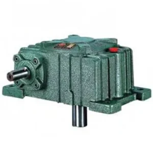
The W Series Worm Gear Reducer is the baseline foot-mounted, solid-shaft worm reducer in the broader W family — a design that predates the WP series and reflects the dimensional tradition that Australian plant engineers have worked with across decades of industrial machinery. Where WP series units carry the IEC-standard dimensional footprint and standardised mounting bolt patterns introduced in later decades, the W series follows its own dimensional convention — taller H dimension relative to centre distance, a deeper output shaft section, and a broader range from size 40 through 200 that accommodates input powers from the smallest fractional-kilowatt indexing drives up to continuous-duty material handling applications. As a worm gear reducer in service across Australian food processing, packaging, and light industrial equipment, the W series offers a proven solid-shaft format with both input and output stub shafts presenting as keyed solid extensions.
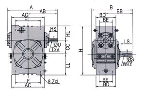
Technical Specifications — W Series Worm Gear Reducer
| Size | Ratio | A (mm) | B (mm) | H (mm) | HL (mm) | Input HS (mm) | Output LS (mm) | Output S (mm) | Weight (kg) |
|---|---|---|---|---|---|---|---|---|---|
| 40 | 1/10–1/60 | 148 | 122 | 125 | 35 | 25 | 28 | 14 | 3.5 |
| 50 | 1/10–1/60 | 175 | 145 | 150 | 35 | 30 | 40 | 17 | 6.0 |
| 60 | 1/10–1/60 | 195 | 165 | 177 | 42 | 40 | 50 | 22 | 8.5 |
| 70 | 1/10–1/60 | 234 | 195 | 215 | 55 | 40 | 60 | 28 | 12.5 |
| 80 | 1/10–1/60 | 264 | 210 | 250 | 65 | 50 | 65 | 32 | 20 |
| 100 | 1/10–1/60 | 322 | 245 | 310 | 80 | 50 | 75 | 38 | 33 |
| 120 | 1/10–1/60 | 385 | 285 | 370 | 95 | 65 | 85 | 45 | 50 |
| 135 | 1/10–1/60 | 435 | 320 | 425 | 105 | 75 | 95 | 55 | 77 |
| 155 | 1/10–1/60 | 494 | 387 | 461 | 103 | 85 | 110 | 60 | 100 |
| 175 | 1/10–1/60 | 548 | 407 | 521 | 123 | 85 | 110 | 65 | 140 |
| 200 | 1/10–1/60 | 688 | 480 | 575 | 130 | 95 | 125 | 70 | 200 |
Ratio 10:1–60:1
Solid Shaft In & Out
Foot-Mounted
Cast Iron Housing
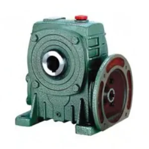
Right-Angle Drive
W Series Engineering Characteristics and Practical Advantages
The W series differs from the WP series in three dimensional parameters that affect how it integrates into existing equipment: the H (total height) dimension relative to the centre distance A is larger in the W series at each size number, the input shaft protrudes from both faces of the housing (enabling through-shaft input from either side), and the output shaft section is deeper with a longer shaft extension at the same size number. These differences reflect the W series’ origins as a general-purpose reducer designed before IEC motor frame standardisation — and they make it the natural replacement for legacy reducers in equipment that was originally designed around the W series dimensional convention.
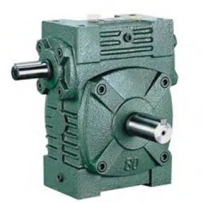
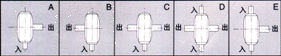
Through-Shaft Input — Drive from Either Side
The W series worm shaft extends from both faces of the housing. Input can be applied from either end, enabling the motor to be positioned on either side of the reducer without changing the reducer orientation. This is a significant layout advantage in machine designs where the motor position is constrained by structural or operator access requirements.
Deeper Output Shaft Section
At each size number, the W series HL (output shaft section depth) and LS (output shaft extension length) exceed the WPA equivalent. This translates to a higher output shaft bearing span and increased permissible overhung load — relevant for chain and belt drives that are positioned at the end of the shaft rather than close to the housing face.
Self-Locking at High Ratios
At ratios 30:1 and above, the worm lead angle produces effective self-locking under static loads — the output shaft holds position without a motor brake. Relevant for gravity-loaded conveyors, gate actuators, and positioning drives where the load must remain stationary on power-off.
Drop-In Legacy Replacement
Decades of Australian food processing and packaging equipment was designed around W series dimensional conventions. When an existing W series reducer reaches end-of-life, a same-size W series replacement fits the existing mounting baseplate, coupling arrangement, and structural bay without modification — reducing replacement time from days to hours.
Wide Size Range — Size 40 to 200
The W series extends to size 200 — covering a wider continuous range than the standard WP series variants and reaching output shaft diameters of 70 mm and weights of 200 kg that suit the largest conveyor and material handling applications in Australian mining and bulk storage facilities.
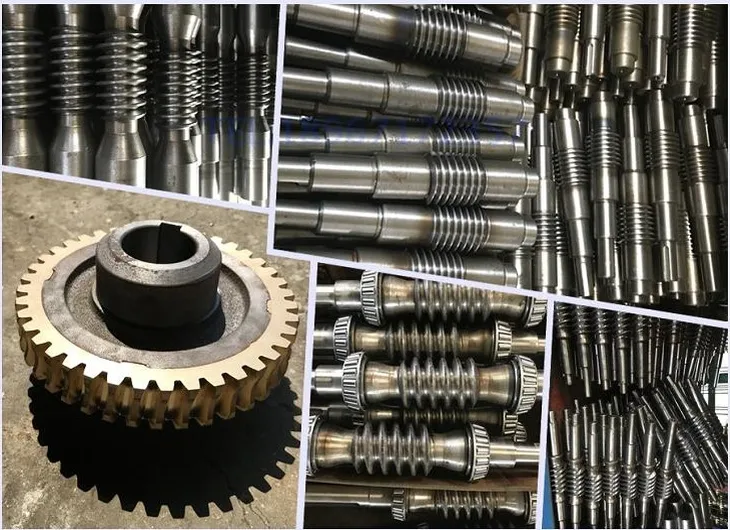
Phosphor-Bronze Worm Wheel — Proven Material
Centrifugally cast phosphor-bronze worm wheel mated against an induction-hardened alloy steel worm shaft — the same gear material couple that has sustained millions of W series units across Australian industry. The material pair is deliberately mismatched so the wheel (the replaceable wear element) sacrifices ahead of the worm shaft (the expensive precision component).
W Series Construction: Design Features That Distinguish It from WP
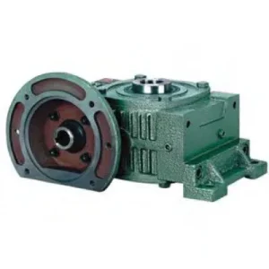
Housing Geometry and Mounting Face Configuration
The W series housing is machined on the four orthogonal faces in the standard way, but the foot pad configuration and the relative proportions of the housing — specifically the ratio of H (total height) to centre distance A — differ from the WP series convention. At size 100, the W series H dimension is 310 mm versus 327 mm in the WPS — a marginal difference — but the AC (housing length) and the BD and BE cross-dimensions reflect a different casting proportion that suits the W series’ deeper output shaft section geometry. When replacing W series units with WP equivalents (or vice versa), these dimensional differences mean the mounting baseplate must be modified even when the centre distance is the same.
Output Shaft Support and Overhung Load
The deeper HL (output shaft section depth) in the W series at each size provides a longer bearing span than the WPA equivalent, which directly increases the permissible overhung load (OHL) from chain sprockets and belt pulleys positioned at the shaft extension midpoint. At size 100, the W series HL of 80 mm versus 65 mm in the WPS means the bearing span is approximately 23% longer — and since OHL capacity scales with the cube of bearing span, the practical radial load capacity at the shaft tip is substantially higher. This makes the W series the technically preferred choice when chain drives are positioned at the far end of the output shaft extension rather than against the housing face.
Input Shaft Through-Configuration and Direction Reversal
Both input shaft stubs are functional in the W series — the worm shaft passes completely through the housing and is supported by bearings at both input faces. The unused stub is covered by a blanking cap supplied with the unit. To reverse the input shaft rotation direction (and thereby reverse the output shaft rotation for a given motor rotation), the 180° input shaft reversal procedure applies — identical to the WPKS procedure. Remove the lower end cover, withdraw the worm shaft, rotate 180°, reinsert, and slowly mesh. This reversal procedure means the W series can accommodate motor position changes from left to right or right to left without changing the output direction — a layout flexibility that is occasionally the deciding factor when integrating the unit into existing machine line-ups.
Where the W Series Finds Its Natural Application Home
The W series is not a direct competitor to the WP series in new-build applications — it is the preservation specification for existing W series machinery and the correct choice when the W series dimensional conventions are the design constraint:
- 🔄 Legacy Equipment Replacement — No Baseplate Modification
Australian food processing and packaging lines built in the 1980s–2000s commonly use W series reducers. When these units reach end of service life, a same-size W series replacement fits the existing mounting baseplate, coupling, and coupling guard without modification — reducing planned shutdown window from two shifts to two hours. Upgrading to a WP series equivalent requires baseplate machining and new coupling selection. - 📦 Packaging Machine Drives — Both-Side Input Flexibility
Packaging machines frequently require the motor to be positioned on a specific side to clear operator access pathways or guard panels. The W series through-shaft input allows the motor to be re-positioned from left to right of the reducer without changing the reducer orientation or affecting the output shaft direction — a layout flexibility that can eliminate a machine redesign. - 🏭 Textile and Printing Machine Drives
Textile machinery and printing press auxiliary drives use W series size 40–80 at 20:1–40:1 for their through-shaft input configuration, which allows intermediate drive take-off points along the input shaft — a drive topology common in older multi-section textile production lines where several machines share a common drive shaft with individual reducers branching off. - 🌾 Agricultural Equipment and Small Farm Machinery
Size 40–70 W series units appear in small-scale Australian agricultural machinery — seed cleaners, small grain augers, and fertiliser spreaders — where the compact size 40 unit (3.5 kg, A = 148 mm) provides the smallest and lightest right-angle worm reduction available in the W family, suitable for battery-operated or small electric motor drives on precision metering equipment. - 🔩 Material Handling Conveyor Drives
Size 155–200 W series units are used on larger Australian materials handling conveyors where the extended HL dimension and larger output shaft diameter provide the overhung load capacity for directly mounted sprockets at 30:1–60:1 ratios, and the self-locking prevents rollback under full-column loading on shutdown without a separate brake mechanism.
Input Options, PTO Shaft Integration, and W Series Accessories
The W series solid-shaft input configuration accepts standard coupling arrangements. For agricultural applications, a PTO shaft assembly connects to the input stub via a standard half-coupling — either a yoke coupling for direct PTO attachment or a jaw coupling for electric motor drives:
Motor and Jaw Coupling (Standard)
A standard jaw coupling connects any IEC or NEMA motor shaft to the W series input stub. Both input stubs are functional — couple to the left or right input face as the motor position dictates. The unused stub remains capped.
Agricultural PTO Shaft
A telescoping PTO shaft with implement-end yoke coupling connects directly to the W series input stub for tractor-driven agricultural applications. Fit a friction slip clutch between the PTO shaft and the reducer input to protect the worm gear set from implement shock events.
Output Coupling and Guard
Output stub accepts any standard jaw or disc coupling bored to the W series S diameter. A polycarbonate coupling guard over the output coupling satisfies Australian WHS rotating machinery guarding requirements. Position the sprocket or pulley as close as practical to the housing face to minimise overhung bending moment.
Breather Vent and Pressure Relief
For continuous-duty applications, a pressure-equalising breather at the filler plug position prevents positive internal housing pressure from weeping oil past the input shaft seals — particularly relevant for W series units operating at high duty cycles in warm Australian plant environments.
Input Shaft Blanking Cap (Unused Side)
The unused input stub must be kept capped with the supplied blanking cap and lip seal to prevent moisture and contamination entry through the unused shaft bore. In dusty Australian agricultural or mining environments, inspect and replace the blanking cap seal at each scheduled oil change.
Lubrication — ISO VG 220
ISO VG 220 mineral gear oil is the standard fill. For cold room applications (below 0°C), specify ISO VG 68 or synthetic VG 100 and pre-warm to above 0°C before initial startup. For high-ratio continuous duty above 30°C ambient, synthetic PAO VG 220 recovers thermal headroom and extends service intervals.
Efficiency, Thermal Limits, and Operating Constraints
The W series shares the same worm gear efficiency characteristics as all single-enveloping cylindrical worm reducers: efficiency drops steeply with increasing ratio. At 10:1, expect 88–92%; at 40:1, expect 65–72%; at 60:1, 55–62%. In Australian applications at 40°C+ ambient temperature in enclosed plant, the thermal rating is almost always the binding design constraint at ratios of 30:1 and above — not the mechanical torque capacity.
| Operating Condition | Limit / Requirement | Action if Exceeded |
|---|---|---|
| Max. input speed | 1,500 rpm | Block VFD above 50 Hz; do not use 2-pole motors |
| Ambient temperature range | –40°C to +40°C | Below 0°C: substitute lower-viscosity oil and pre-warm; above 40°C: synthetic oil or cooling fin kit |
| Housing temperature limit | ≤ 90°C (oil) | Step up one frame size or switch to synthetic oil if housing temperature exceeds 70°C at rated load |
| Input direction | Either shaft end | 180° reversal procedure required to change output rotation direction; do not force-mesh shafts during reassembly |
W Series Maintenance Schedule
| Interval | Task | W Series Note |
|---|---|---|
| First 500 hours | Oil drain and refill | Critical run-in flush — bronze wheel particles accumulate; check both input shaft seals and the unused stub blanking cap |
| Every 2,500 hours | Oil change; inspect all seals | Inspect unused input stub blanking cap and lip seal — often neglected and the most common contamination entry point in W series units |
| Every 5,000 hours | Bearing clearance check; output shaft radial play | W series HL dimension provides longer output bearing span — but check radial play regardless; >0.12 mm warrants replacement |
| At direction reversal | 180° shaft reversal procedure | Slowly rotate shafts by hand until teeth mesh — never force-insert; replace oil fill after reversal to remove any metallic debris from disassembly |
For W series replacement specifications, legacy equipment dimensional cross-referencing, and application-specific selection support for Australian plant, the team at our worm gearbox technical portal can confirm drop-in compatibility and provide dimensional drawings. Submit enquiries and replacement identification requests via the technical enquiry page.