Description
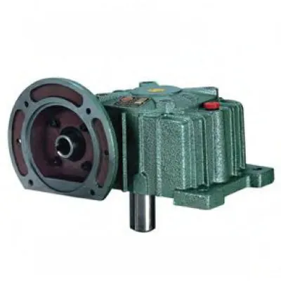
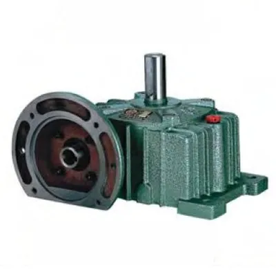
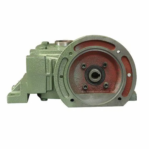
The DX & DO Series Single Standard Worm Gear Reducer — catalogued as WPDX and WPDO — represents the most versatile configuration in the WP family: a worm reducer that simultaneously integrates a motor-direct IEC flange on the input side and a dual-output-shaft arrangement on the driven side. Where the WPO and WPX series offer dual output with separate motor coupling, and the WPDA offers motor-direct input with single output, the WPDX and WPDO close the gap by delivering all three features in a single sealed housing. The result is a right angle worm gearbox capable of driving two co-axial (WPDO) or 90°-offset (WPDX) loads directly from a flanged motor without any external coupling, distribution chain, or supplementary splitter box. Sizes 50 through 155 cover input powers from 0.18 kW to 5.5 kW at standard gear ratios of 10:1 to 60:1.
Technical Specifications — DX & DO Series (WPDX / WPDO) Worm Reducer
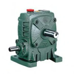
WPDX (DX) — Shaft Configuration
Motor flange input + dual output shafts at 90° offset. One output co-axial with motor input; second output exits at right angle. Suits L-shaped drive layouts within a single compact unit.
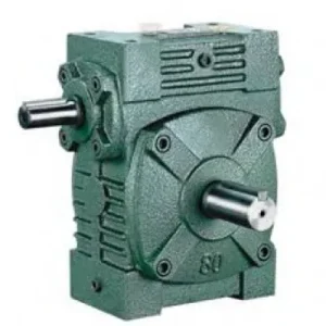
WPDO (DO) — Shaft Configuration
Motor flange input + twin co-axial output shafts on opposite faces. Both output stubs rotate at identical speed. Ideal for parallel twin-driven machinery with a direct-flanged motor.
| Size | Power (kW) | Ratio | A (mm) | B (mm) | BC (mm) | Output LS (mm) | Flange LA (mm) | Weight (kg) |
|---|---|---|---|---|---|---|---|---|
| 50 | 0.18 | 1/10–1/60 | 165 | 145 | 50 | 40 | 115 | 7 |
| 60 | 0.37 | 1/10–1/60 | 185 | 165 | 55 | 50 | 130 | 10 |
| 70 | 0.37 / 0.75 | 1/10–1/60 | 209 | 195 | 65 | 60 | 130 | 15 |
| 80 | 0.75 / 1.5 | 1/10–1/60 | 242 | 210 | 70 | 65 | 165 | 23 |
| 100 | 1.5 | 1/10–1/60 | 310 | 245 | 90 | 75 | 165 | 36 |
| 120 | 2.2 / 3.0 | 1/10–1/60 | 361 | 285 | 100 | 85 | 215 | 55 |
| 135 | 3.0 / 4.0 | 1/10–1/60 | 412 | 320 | 110 | 95 | 215 | 80 |
| 155 | 5.5 | 1/10–1/60 | 442 | 392 | 140 | 110 | 265 | 120 |
Input Flange Dimensions — IEC B5 Interface (WPDX / WPDO)
| Size | Flange Register LZ (mm) | Bolt Circle LB (mm) | Bolt Size | Input Bore Q (mm) |
|---|---|---|---|---|
| 50 | 140 | 95 | M8 | 25 |
| 60 | 160 | 110 | M8 | 35 |
| 70 | 160 / 200 | 110 / 130 | M8 / M10 | 35 / 45 |
| 80 | 200 | 130 | M10 | 45 / 55 |
| 100 | 200 | 130 | M10 | 55 |
| 120 | 250 | 180 | M12 | 65 |
| 135 | 250 | 180 | M12 | 65 |
| 155 | 300 | 230 | M12 | 85 |
Dual Output Shafts
IEC B5 Flange Input
10:1 – 60:1 Ratios
WPDX: 90° Offset
WPDO: Co-Axial
Why the WPDX and WPDO Eliminate Three Components in One Housing
A conventional dual-output worm drive installation involves four separate units: a motor, a flexible coupling, a WPO/WPX reducer, and some form of output distribution hardware. The WPDX and WPDO collapse this into a single sealed assembly. The engineering benefits are cumulative rather than additive — each eliminated component removes not just its own cost but also its alignment requirement, its failure mode, and its guarding obligation under Australian WHS regulations.
Zero External Coupling Required
The IEC B5 flange eliminates the input coupling, coupling guard, and guard interlock entirely. In high-care food processing environments this removes the coupling as a potential catch point for product, cleaning chemicals, and pest entry — a genuine hygiene risk reduction, not just a cost saving.
Synchronised Twin Output — Factory Guaranteed
Both output shafts share the same worm wheel — the speed ratio between them is exactly 1:1 with zero accumulated phase error. In packaging and grain handling applications requiring matched auger or conveyor speed, this eliminates the chain-stretch and sprocket-wear phase drift that occurs in external synchronisation drives.
Compact Integrated Footprint
Motor + WPDX/WPDO replaces motor + base + coupling + WPO/WPX + external distribution hardware. The integrated unit is typically 30–45% shorter in the direction of the motor axis compared to the separately assembled equivalent, a meaningful gain when retrofitting drives in existing plant with fixed structural bay dimensions.
Single Lubrication Point for Entire Drive
One oil fill, one oil drain, one seal inspection covers the entire driving and driven gear set. In remote Australian agricultural installations where maintenance personnel are scarce, the elimination of chain lubrication, tensioner adjustment, and independent coupling greasing reduces planned maintenance to a single 30-minute oil change every 2,500 hours.
WPDX 90° Output Geometry
The WPDX routes one output at 90° to the other, enabling true L-shaped drive arrangements in a single housing. Agricultural spreader rotors, poultry processing transfer conveyors, and turntable outfeed systems all require this geometry — the WPDX delivers it without any external bevel stage.
Self-Locking at High Ratios
At 30:1 and above, both output shafts are held stationary on power-off without any additional mechanical brake — the worm mesh friction provides the holding torque. In twin-auger grain handling systems, this prevents dual-auger rollback under full-column loading when the motor de-energises at shift end.
Housing Architecture: Engineering Both the Flange and the Dual Output
Three-Function Housing Casting
The WPDX/WPDO housing is the most geometrically complex casting in the WP family, combining three precision-machined functional faces: the IEC B5 input flange on the motor side, the primary output shaft bore, and the secondary output shaft bore (at 90° for WPDX or opposite-face co-axial for WPDO). All three features are machined in a controlled sequence in a single holding to ensure that the angular relationship between motor shaft, primary output, and secondary output is maintained within the tolerance required for the application — typically ±0.05° for the flange concentricity and ±0.1° for the secondary output shaft perpendicularity (WPDX) or parallelism (WPDO).
Worm Wheel Hub and Dual Output Shaft Connection
Both output shafts are connected to the worm wheel through the wheel hub. In the WPDO, both shafts extend from the same wheel hub on opposite sides of the housing — sharing the hub equally, so that overhung loads from both shafts act in opposing directions and partially cancel at the hub. In the WPDX, the secondary shaft exits at 90°, which means a bevel step is incorporated into the housing between the primary worm wheel axis and the secondary shaft axis — a compact internal bevel that avoids any requirement for an external bevel gearbox to achieve the 90° secondary drive.
Combined Load Capacity and Torque Sharing
The rated output torque of the WPDX/WPDO refers to the total torque available across both output shafts combined. If both shafts are loaded equally, each carries 50% of the rated combined torque. If one shaft is lightly loaded, the other can carry more — but the total must not exceed the rated combined figure. The input power sizing must account for the sum of both output loads divided by the mesh efficiency at the selected ratio. This combined torque calculation is the single most common specification error observed when engineers unfamiliar with dual-output reducers first work with this series.
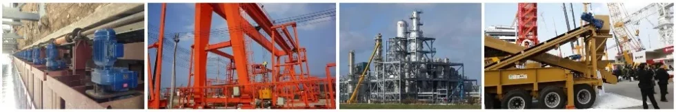
Applications Where WPDX and WPDO Replace Multiple Components
The WPDX and WPDO are not general-purpose substitutes for single-output reducers. Each application below represents a scenario where their specific combination of motor-direct input and dual output resolves a real engineering constraint:
- 🌾 Twin-Auger Grain and Seed Handling
WPDO size 100–120 at 30:1–40:1 drives matched grain auger screws from a single flanged motor. The co-axial dual output guarantees zero speed differential between screws — eliminating grain bridging caused by auger speed mismatch — while the motor-direct format removes the coupling that would otherwise need guarding in a grain-dusty environment where ignition hazards are managed under Australian Standard AS 60079. - 🍇 Fermentation Tank Dual-Paddle Agitators
Winery and distillery fermentation tanks with two paddle shafts entering from opposite tank faces use WPDO top-mounted on the tank lid. The flanged motor mounts above the reducer; both paddle shafts receive identical torque and speed from the co-axial dual output without any external power distribution hardware below the tank lid. - 🚜 PTO-Alternative Electric Drives for Multi-Rotor Spreaders
Agricultural spreaders transitioning from tractor PTO to electric motor drive use WPDX units where the L-shaped output geometry suits the spreader rotor and cross-conveyor arrangement. The WPDX at size 80–100 at 20:1–30:1 ratio eliminates the bevel splitter box that PTO-driven layouts require, while the direct motor flange suits standard IEC 80–100 frame motors from any Australian supplier. For detailed guidance on the PTO-to-electric transition and appropriate PTO shaft interface configurations, our technical team can assist with the drivetrain redesign. - 📦 Packaging Machine Infeed & Outfeed Pair
Parallel infeed and outfeed belt conveyors flanking a packaging machine require matched speed with single-motor economy. WPDO size 60–80 at 20:1 eliminates two independent motor-reducer pairs and their individual VFDs, replacing them with one WPDO plus one VFD. Control is simplified to a single speed reference. - 🏭 Poultry Processing Line Corner Transfers
WPDX units in poultry processing drive an overhead shackle conveyor (primary output) and a 90°-direction product transfer conveyor (secondary output) from a single flanged washdown-rated motor. The enclosed, motor-direct format suits the high-pressure water cleaning environments in Australian food-grade processing areas without requiring a separate motor base that would be difficult to clean underneath. - 💧 Water Treatment Dual-Mechanism Drives
WPDO size 100 drives a primary sludge scraper and a secondary chemical dosing screw from a single flanged motor. By selecting different sprocket ratios on each output stub, proportional flow rates for chemical dosing relative to sludge volume are maintained mechanically — without an additional control loop or secondary motor.
PTO Integration and Associated Drive Components
Although primarily designed for direct IEC motor mounting, the WPDX and WPDO are also used in Australian agricultural drivetrains where PTO power is the source. The following components define a complete WPDX/WPDO drivetrain:
IEC B5 Flanged Motor
Standard 4-pole TEFC motors at 1,450 rpm. For VFD operation below 25 Hz, specify a force-ventilated (IC416) motor. Confirm motor D-end flange register, bolt circle, shaft diameter, and shaft length against the WPDX/WPDO flange table before ordering to avoid seating issues at installation.
PTO Shaft with Flange Adaptor (Agricultural)
For tractor PTO input, a telescoping PTO shaft with a flange-end adaptor engages the WPDX/WPDO input flange bore. The combined input torque for both output loads must be calculated and the PTO shaft rated accordingly — dual-output configurations carry twice the single-output input torque for the same output load per shaft.
Input Torque-Limiter Clutch
Essential when one output shaft can jam while the other continues to run — a failure mode unique to dual-output units. A torque-limiting slip clutch on the input shaft protects the worm gear set from full motor torque being concentrated at the jammed output. Set slip torque at 1.5× combined rated input torque.
Dual Output Couplings (×2)
Both output stubs require jaw or disc couplings, each sized for their respective driven load torque. Use identical coupling types and element hardness on both outputs where matched torsional stiffness is required (precision indexing) — mismatched coupling flexibility between the two outputs introduces phase drift under dynamic load changes.
Thermal Monitoring Port (Sizes 100+)
Dual-output operation imposes the combined load of both outputs on the single worm mesh, increasing heat generation compared to a single-output unit at the same size. Sizes 100 and above include a thermal sensor port — a PT100 connected to the plant SCADA provides early warning of oil overtemperature before seal damage occurs.
Pressure-Equalising Breather
Three shaft penetrations (one input flange bore, two output shaft seals) increase the total sealing surface compared to a single-output unit. A pressure-equalising breather replacing the standard oil filler prevents positive housing pressure from forcing oil past the output shaft seals — particularly important in high-duty continuous operation.
Choosing Between WPDX and WPDO: Application-Based Decision Framework
| Decision Criterion | WPDO (DO) | WPDX (DX) |
|---|---|---|
| Output shaft geometry | Co-axial, 180° apart | 90° offset |
| Ideal layout | Parallel twin drives in-line | L-shaped drive arrangements |
| Bearing load balance | Opposing loads partially cancel | Check OHL per stub independently |
| Housing axial length (output direction) | Longer — spans both output stubs | Shorter on primary axis |
| Internal bevel stage | None required | Built-in for 90° secondary output |
| Example applications | Fermentation paddles, twin augers | Spreader rotors, poultry transfers |
Sizing the WPDX / WPDO: Avoiding the Combined-Torque Specification Error
The most frequent specification error with dual-output units is treating each output shaft as if it could carry the full rated torque independently. This is incorrect. The correct sizing methodology:
Calculate Each Output Shaft’s Required Torque
Determine T1 and T2 (Nm) for the two driven loads independently. Apply the appropriate service factor to each (shock loads, duty cycle, startup torque) to get the peak torque requirement per shaft.
Sum the Combined Output Torque
T_combined = T1 + T2. Select a WPDX/WPDO size whose rated output torque at the selected ratio equals or exceeds T_combined. Do not select based on T1 or T2 alone.
Verify Thermal Rating Against Total Input Power
P_input = T_combined / (ratio × η). At high ratios in Australian summer ambient temperatures (40°C+), the thermal rating is typically the binding constraint. Check P_th for the selected size against P_input; if thermal limit governs, step up one frame size or specify synthetic PAO oil.
Confirm Motor Frame and IEC Flange Match
Cross-reference the motor IEC frame code against the WPDX/WPDO flange table. Record this on the project BOM — when the motor must be replaced in the field, an incorrect replacement frame is the single most common cause of delayed recommissioning on dual-output motor-flange units.
Maintenance Considerations Specific to the Dual-Output Motor-Flange Configuration
The WPDX and WPDO present a unique maintenance profile: three shaft penetrations (one input bore, two output stubs) create more potential seal leak points than any other single unit in the WP family. A structured inspection protocol targeting these points prevents the majority of field failures:
| Interval / Trigger | Task | Dual-Output Specific Note |
|---|---|---|
| First 500 hours | Oil drain and refill (run-in flush) | Inspect both output shaft seals for weeping — bronze run-in particles can score seal lips |
| Every 2,500 hours | Full oil change; inspect all three shaft seals | Replace any seal showing oil weeping — dual-output units develop positive internal pressure faster due to larger total swept volume |
| Every 5,000 hours | Motor flange bolt torque check; both output shaft bearing clearance checks | Check radial play at both output stubs: >0.1 mm indicates bearing wear — chain/belt loads accelerate wear versus single-output |
| Motor replacement | Verify replacement motor IEC frame code | Log original motor frame on both the gearbox label and the plant maintenance schedule |
| If one output jams | Inspect worm wheel for overload damage | Full motor torque on one jammed output can cause concentrated tooth contact damage even with motor overload trip — inspect before returning to service |
For specification calculations, dimensional drawings, and IEC motor frame cross-referencing for the DX & DO series across Australian applications, the engineering team at our worm gearbox technical portal provides application-specific support. For agricultural drivetrain integration — including PTO-to-electric-motor conversion projects and multi-output implement drive design — additional guidance is available through our contacts page. Further resources on agricultural power transmission system integration can be found at gearboxagricultural.com.