Description

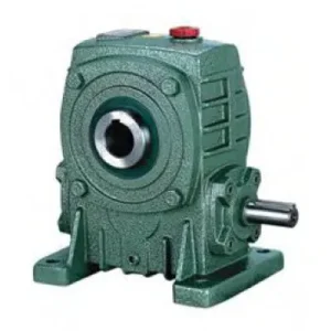
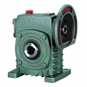
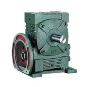
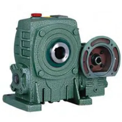
Technical Specifications — EA Series (FCEA) Double Worm Gear Reducer
How to Read the Size Specification — Stage Pairs
Each FCEA size is specified as a Stage 1 – Stage 2 pair (e.g., “60-100”). The first number is the housing size of the first-stage worm reducer (input side, higher speed, smaller housing). The second number is the housing size of the second-stage worm reducer (output side, lower speed, larger housing). Overall ratio = Stage 1 ratio × Stage 2 ratio. Available overall ratios: 200:1 through 900:1. Input: IEC B5 flange (FCEA). Output: solid shaft (S, W×Y).
Available Overall Ratios — FCEA Double Worm
1 / 300
1 / 400
1 / 500
1 / 600
1 / 800
1 / 900
At 1,450 rpm input (4-pole motor): output speeds from 7.25 rpm (1/200) down to 1.6 rpm (1/900)
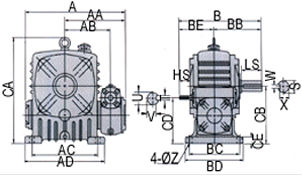
| Stage Pair | Overall Ratio | A (mm) | B (mm) | AB (mm) | BB (mm) | BC (mm) | Input HS (mm) | Output LS (mm) | Output S (mm) | Output W (mm) |
|---|---|---|---|---|---|---|---|---|---|---|
| 40–60 | 200–900 | 232 | 195 | 112 | 110 | 105 | 25 | 50 | Ø22 | 7 |
| 50–80 | 200–900 | 289 | 247 | 132 | 140 | 135 | 30 | 65 | Ø32 | 10 |
| 60–100 | 200–900 | 352 | 294 | 161 | 155 | 155 | 40 | 75 | Ø38 | 10 |
| 70–120 | 200–900 | 417 | 325 | 195 | 185 | 180 | 40 | 85 | Ø45 | 12 |
| 80–135 | 200–900 | 462 | 370 | 211 | 210 | 200 | 50 | 95 | Ø55 | 15 |
| 100–155 | 200–900 | 542 | 442 | 257 | 252 | 220 | 50 | 110 | Ø60 | 15 |
| 120–175 | 200–900 | 585 | 492 | 275 | 262 | 250 | 65 | 110 | Ø65 | 18 |
Ratio 200:1 – 900:1
IEC B5 Flange Input (FCEA)
Solid Shaft Output
7 Stage-Pair Sizes
Self-Locking (All Ratios)
Why Two Worm Stages? The Engineering Case for Ratios Above 60:1
A single-stage worm reducer is mechanically limited to approximately 60:1 ratio in the standard catalogue range. Beyond this, the worm lead angle becomes so shallow that efficiency falls below practical levels and the gear geometry cannot be manufactured to reliable tolerances at production cost. Two-stage worm reducers solve this by keeping each individual stage within the 10:1–60:1 range where worm gear efficiency and tooth geometry are well-optimised, then multiplying the ratios. Three consequences follow that define the FCEA’s application envelope:
⚡ Output Speed: 1.6 – 7.25 rpm
At a standard 1,450 rpm 4-pole motor input: 1/900 ratio gives 1.6 rpm output; 1/200 gives 7.25 rpm. This covers the ultra-slow output speed range that is required for valve actuators, stirrer drives, and astronomical or solar tracking equipment — speeds that no single-stage reducer can deliver without an additional gear stage.
🔒 Self-Locking — All Ratios, Both Stages
Both worm stages are inherently self-locking. At any ratio from 200:1 to 900:1, the output shaft holds stationary on power-off without a brake — both worm meshes resist back-driving simultaneously. For gate valve actuators and loaded hoists, this double self-locking provides a mechanical safety margin that single-stage reducers with external brakes cannot match in terms of reliability under sustained static load.
📦 One Housing — Replaces Multi-Unit Arrangements
Achieving 400:1 or 600:1 with separate reducers requires either a worm + additional gear stage, or two separate worm units with a connecting shaft, coupling, and intermediate bearing support. The FCEA replaces all of this with a single self-contained housing — one oil fill, one maintenance point, one mounting interface, one unit to specify and purchase.
⚠️ Two-Stage Efficiency — Always Verify Thermal Rating
Two-stage worm reducers have lower overall efficiency than single-stage — approximately η_overall = η_stage1 × η_stage2. At 400:1 where each stage operates at 20:1 (typical split), individual stage efficiency ≈ 75–80%, giving overall ≈ 56–64%. This means 36–44% of input power becomes heat in the housing. In 40°C+ Australian summer ambient and continuous duty, thermal rating is almost always the governing constraint at high ratios — not mechanical torque capacity. Always verify the thermal rating at your specific input power, ratio, and ambient temperature before confirming the FCEA specification.
Six Advantages That Make the FCEA the Preferred Specification for Ultra-High Reduction
Single-Unit 200–900:1 — No Multi-Gearbox Arrangement
The FCEA eliminates the second gearbox, intermediate coupling, intermediate shaft, and intermediate bearing support that multi-unit arrangements require. In a gate valve actuator where the available drive compartment is a fixed size, the self-contained FCEA housing fits in the space that two separate units plus their connecting hardware would not. One unit, one maintenance point, one oil change, one spare parts specification.
Double Self-Locking — Both Stages Hold
Both FCEA worm stages self-lock simultaneously on power-off. The output shaft is held by two independent self-locking mechanisms in series — if one stage somehow loses locking integrity under extreme conditions (worn gear tooth, lubrication failure), the other stage still holds. For gate actuators controlling flow in critical Australian water infrastructure, this double locking provides a mechanical redundancy that single-stage reducers fundamentally cannot.
IEC Flange Input — Motor Direct (FCEA Variant)
The FCEA variant adds an IEC B5 motor flange to the first stage input, eliminating the input coupling. In actuator and slow-drive applications where the motor is typically small (0.12–0.75 kW) and space is limited, removing the motor base and coupling body from the package reduces the overall drive length substantially. Any IEC B5 frame motor of the correct power bolts directly — no alignment jig, no custom bracket, no coupling spider to replace.
Matched Stage Pairs — Optimised Per-Stage Loading
The FCEA stage pairing (e.g., 60-100) is not arbitrary — the first-stage size is engineered to handle the high-speed, low-torque input without oversizing, while the second-stage size is engineered to handle the low-speed, high-torque output without exceeding its rated output torque. Selecting matched FCEA stage pairs from the catalogue ensures both stages are correctly loaded; mismatching stages from different FCEA configurations is a specification error that leads to premature failure of the underrated stage.
Single Oil Fill — Both Stages Lubricated Together
The integrated FCEA housing shares a common oil reservoir across both worm stages, lubricating both gear sets from one fill point. Separate gearbox arrangements require two oil changes at every service interval. The FCEA requires one. In remote Australian locations where each maintenance activity incurs travel cost, halving the oil change activity per service is a tangible lifecycle cost reduction.
Compact vs Multi-Unit Arrangement
A separate 20:1 worm plus a 20:1 second-stage worm plus the connecting shaft, coupling, intermediate bearing support frame, and two motor bases occupies substantially more space than an FCEA 60-100 at 400:1. For OEM gate actuators, compact stirrer drive heads, and solar tracker drive pods, this space difference is design-determining — the FCEA makes the drive package fit; separate units do not.
Applications — Where 60:1 Is Insufficient and a Single Unit Must Deliver More
- 🌊 Gate Valve and Sluice Actuators — Double Self-Locking (self-locking worm gearbox)
FCEA 60-100 at 400:1–600:1 for slow-rotation gate valve actuators in Australian water treatment and irrigation infrastructure. At 600:1, a 4-pole motor turning at 1,450 rpm produces 2.4 rpm output — correct for the slow valve travel rate required in large diameter sluice gates where rapid actuation causes hydraulic shock. Both worm stages self-lock simultaneously on power-off, holding the gate at any intermediate position without hydraulic pressure or an electrical brake. The IEC flange input eliminates the input coupling from the actuator housing — critical in waterproof actuator enclosures where coupling-gap ingress is a seal design challenge. - 🧪 Slow Stirrer and Fermentation Drives
FCEA 50-80 at 300:1–400:1 for slow-speed fermenter and biogas stirrer drives. Anaerobic digestion and fermentation vessels require very slow paddle rotation (3–5 rpm) to avoid disrupting the microbial culture while maintaining homogeneous mixing. A single-stage reducer at 60:1 with a 1,450 rpm motor gives 24 rpm — far too fast. The FCEA at 300:1 gives 4.8 rpm directly from the motor without additional gear stages, VFD frequency reduction to unusably low frequencies, or external chain reduction. The compact FCEA housing mounts directly on the vessel top flange with the IEC motor attached to the reducer input face. - ☀️ Solar Tracker and Antenna Azimuth Drives
FCEA 40-60 to 60-100 at 200:1–900:1 for single-axis solar tracker azimuth drives and satellite dish or radio antenna positioning systems in Australian remote installations. Solar trackers need rotation rates of 0.004–0.01 °/second to follow the sun — achievable directly from a small IEC motor through a 600:1–900:1 FCEA reduction. The IEC flange input eliminates the coupling from the drive pod, reducing maintenance requirements on installations that may be serviced only once or twice annually. The double self-locking holds the tracker panel at the correct angle during overnight wind loading without any locking actuator or brake. - 🏭 OEM Positioning and Indexing Drives — Low Speed High Torque
FCEA 70-120 at 400:1–600:1 for OEM machine positioning drives where the output shaft must rotate at 2–4 rpm with high output torque at a physically compact drive head. Rotary indexing tables, turntable drives, and slow-speed positioning axes in Australian industrial automation use FCEA where single-stage reducers require additional gear reduction stages that the machine envelope cannot accommodate. The high ratio also provides fine position control resolution when paired with an encoder — one motor revolution produces less than 1° of output rotation at 900:1. - 🌾 Precision Agricultural Equipment — Slow Feed Rate Drives
FCEA 50-80 at 300:1–500:1 for precision agricultural seeding rate control, slow-speed seed singulation, and fertiliser micro-dosing drives in high-precision Australian cropping machinery. The compact FCEA package fits within implement frames where a two-unit gear train would not. Where PTO shaft input is preferred over electric motor for implement drives, a PTO-to-IEC flange adaptor connects to the FCEA input face — refer to agricultural PTO shaft specifications for adaptor sizing. For broader agricultural gearbox integration guidance, refer to gearboxagricultural.com.
FCEA Selection Procedure — Stage Pair, Ratio, and Thermal Check
Determine Required Output Speed
Calculate required output rpm. Input motor speed at 50 Hz ≈ 1,450 rpm for 4-pole. Ratio required = 1,450 / required output rpm. Round to the nearest available FCEA ratio (200, 300, 400, 500, 600, 800, 900). Always round UP to the next available ratio if between values — this gives lower output speed, not higher, which is the safe direction for most actuator and slow-drive applications.
Calculate Required Output Torque
T_output = P_input × ratio × η_overall / (2π × n_input / 60). Apply service factor to the calculated nominal torque. For actuator and positioning drives with smooth loading, SF = 1.0–1.25. For drives with inertial shock at startup or reversal, SF = 1.5–2.0. Select FCEA stage pair where rated output torque ≥ T_output × SF at the selected ratio.
Verify Thermal Rating — Critical Step
Heat generation at high ratios is the primary constraint. Calculate heat generated = P_input × (1 – η_overall). At 500:1, η_overall ≈ 50%, so half of input power becomes heat. At 40°C Australian ambient in continuous duty, the FCEA thermal rating is reduced by approximately 15% from the 25°C reference. Submit your duty cycle, ambient temperature, and required ratio to the technical team for a confirmed thermal assessment before finalising the specification.
Select FCEA Stage Pair from Catalogue
Match output torque requirement to the smallest FCEA stage pair that satisfies it. Do not select stage pairs larger than necessary — oversizing increases housing size, weight, and cost without proportionate benefit in a thermally constrained application. In thermal-limit conditions, a larger stage pair provides more surface area for heat dissipation; this is the one case where deliberate stage pair upsizing may be technically justified.
Verify IEC Motor Frame
Confirm motor IEC frame matches FCEA input flange dimensions (HS input bore, stage-pair-specific flange bolt circle). For actuator applications, the motor is typically 0.12–0.55 kW in IEC 63–71 frame — confirm the specific motor’s shaft length against the FCEA input bore depth (T×V). The FCEA’s first stage is small (size 40–70) and input bore depth is limited; a motor shaft that bottoms out prevents correct flange seating.
Commission at Specified Duty and Monitor Temperature
During initial commissioning, monitor housing temperature at 30, 60, and 120 minutes of continuous operation. If housing surface temperature exceeds 70°C at 25°C ambient reference conditions, reconsider the duty cycle, switch to PAO synthetic oil, or contact the technical team. The FCEA housing temperature is the single most reliable indicator of whether the unit is within its rated operating envelope.
Drive Accessories and PTO Integration for the FCEA
PTO Adaptor — Speed Reduction Before FCEA
Tractor PTO output speed is 540 rpm (ground PTO) or 1,000 rpm (independent PTO). At 540 rpm input into an FCEA at 600:1, output speed = 0.9 rpm — suitable for very slow drives. A yoke-end IEC flange adaptor with friction slip clutch (1.5× rated input torque) connects PTO to the FCEA first-stage input face. Note: the FCEA first stage is small (size 40–70); the input bore depth is limited and the PTO yoke adaptor must be dimensionally verified against the first-stage HS and T×V bore specification.
Micro Motor — Low Power Actuator Applications
At FCEA stage pair 40-60, the first-stage input bore (HS = 25 mm) is sized for small IEC motors in the 63–71 frame range at 0.12–0.25 kW. For gate actuators where the combined motor + FCEA weight must remain below 15 kg, confirm the specific micro motor IEC frame against the FCEA 40-60 flange dimensions before ordering — small-frame IEC motors vary in shaft length and keyway dimensions between manufacturers.
PAO Synthetic Oil — Mandatory for Continuous Duty
For FCEA units in continuous duty (not intermittent actuator cycling), PAO synthetic ISO VG 220 is recommended, not optional. The two-stage heat generation at high ratios combined with Australian ambient temperatures in continuous operation will typically bring a mineral-oil-filled FCEA to its thermal limit before a PAO-filled unit. Synthetic oil also lubricates both worm stages more effectively at the low inter-stage shaft speed, where the oil splash from the first stage must adequately reach the second stage gear mesh.
External Cooling Fan — High-Duty Applications
For continuous-duty FCEA applications at high ratios (≥ 500:1) in enclosed or hot environments, an external cooling fan mounted on the housing can double the effective thermal dissipation surface area and raise the allowable continuous input power by 15–25%. If the FCEA thermal rating calculation shows marginal headroom at your ambient temperature and duty cycle, a cooling fan is the most cost-effective thermal mitigation before moving to the next larger stage pair.
Output Shaft Coupling
The FCEA solid output shaft (S diameter, LS length, W×Y key) connects to the driven load via a standard coupling or direct key-in-hub mount. At high ratios (600:1+), the output torque is very high for the power level — at 600:1 with 0.25 kW input, output torque ≈ 0.25 × 600 × 0.5 (efficiency) / (2π × 1450/60) ≈ 370 Nm at size 60-100 output. Select the coupling for this torque, not for the input power rating.
Mounting Orientation — Verify Oil Fill
The FCEA has two oil fill/drain points — one per stage. Both stages must have correct oil levels in the installed orientation. Non-standard orientations (stage axis vertical, inverted, or tilted) require specific fill levels for each stage independently. Submit your installed orientation to the technical team before commissioning — incorrect oil level in either stage independently is the most common cause of premature FCEA failure in OEM gate actuator installations.
Maintenance Schedule — FCEA Double Worm Series
| Interval | Task | FCEA Two-Stage Note |
|---|---|---|
| First 500 hr | Flush and replace oil in BOTH stages; flange bolt check | Two drain/fill points — both must be drained and refilled; using one fill point to try to fill both stages results in oil starvation in one stage, accelerating bronze wheel wear in the underfilled stage within the first 1,000 hours |
| Every 2,500 hr | Full oil change both stages; all seals; flange face check | Check housing temperature trend against first 500-hour baseline — an increasing temperature trend at constant ambient conditions indicates one stage worm wheel wear approaching end of life; schedule inspection before complete failure |
| Every 5,000 hr | Remove inspection covers both stages; worm wheel visual; inter-stage bearing check | The inter-stage shaft (connecting first-stage output to second-stage input) runs at intermediate speed — inspect its bearings independently; inter-stage bearing failure mode is different from both input and output bearing failure |
| At worm wheel replacement | Replace the worn-stage wheel; inspect the other stage before reassembly | Replacing one stage’s worm wheel while the other remains in service is correct practice — the two stages wear at different rates due to different torque levels. Do not replace both wheels simultaneously unless both show wear beyond the acceptable threshold |
For FCEA stage pair selection, thermal rating verification at your duty cycle and ambient temperature, oil fill orientation guidance for non-standard actuator mounting angles, and procurement scheduling for Australian gate valve actuator and solar tracker projects, the engineering team at our worm gearbox technical portal provides application-specific support. Submit your required output speed, output torque, duty cycle, and ambient temperature for a confirmed FCEA stage pair and ratio recommendation. Contact us via the technical enquiry page.