Description
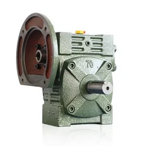
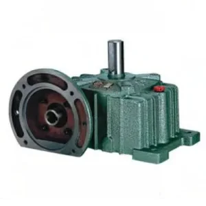
The EWA Series Double Worm Gear Reducer pairs a through-shaft solid input — motor coupling placeable on either first-stage housing face — with a WA-class deep hollow bore output on the second stage, achieving 200:1 to 900:1 reduction within one integrated housing. Where the EDA demands a fixed IEC flange motor position, the EWA keeps that choice open: the same unit ships to a left-hand motor installation and a right-hand motor installation without change. The WA bore depth provides substantially more key face engagement than a standard hollow bore at the same diameter, handling the very high output torques that extreme reduction ratios generate from even small input motors. Stage pairs run from 40-60 through 135-200, covering output bore diameters from Ø22 mm to Ø70 mm. For Australian slow-speed shaft-mount applications — gate valve actuators, digester impeller drives, solar tracker azimuth mechanisms, and precision metering implements — where motor position flexibility and output coupling elimination must coexist, the EWA resolves both simultaneously.
Technical Specifications — EWA Series Double Worm Gear Reducer
Input: Through-Shaft — Either Housing Face
Solid shaft stub exits both first-stage faces. Motor jaw-couples to either side. Unused stub sealed with blanking cap. Motor orientation freely selectable at installation.
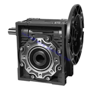
Output: WA-Class Deep Hollow Bore
Driven shaft seats directly into keyed deep bore — no output coupling required. Deep bore distributes high two-stage output torques over large key face area. Shrink disc recommended for stage pairs 80-135 and above.
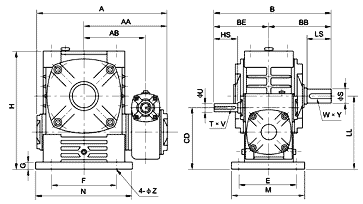
| Stage Pair | Overall Ratio | A (mm) | B (mm) | H (mm) | HL (mm) | Input HS (mm) | Output LS (mm) | Output S (mm) | Key W×Y |
|---|---|---|---|---|---|---|---|---|---|
| 40–60 | 200–900 | 232 | 201 | 120 | 100 | 25 | 50 | Ø22 | 7×4 |
| 50–80 | 200–900 | 297 | 245 | 163 | 133 | 30 | 65 | Ø32 | 10×4.5 |
| 60–100 | 200–900 | 337 | 283 | 200 | 160 | 40 | 75 | Ø38 | 10×4.5 |
| 70–120 | 200–900 | 412 | 325 | 240 | 190 | 40 | 85 | Ø45 | 12×4.5 |
| 80–135 | 200–900 | 475 | 370 | 270 | 215 | 50 | 95 | Ø55 | 15×5 |
| 100–155 | 200–900 | 549 | 430 | 290 | 235 | 50 | 110 | Ø60 | 15×5 |
| 120–175 | 200–900 | 605 | 492 | 335 | 280 | 65 | 110 | Ø65 | 18×6 |
| 135–200 | 200–900 | 674 | 565 | 375 | 310 | 75 | 125 | Ø70 | 20×7 |
Available Overall Ratios and Output Speeds at 1,450 rpm Input
1/300 → 4.83 rpm
1/400 → 3.63 rpm
1/500 → 2.9 rpm
1/600 → 2.4 rpm
1/800 → 1.8 rpm
1/900 → 1.6 rpm
200:1–900:1
Through-Shaft Input
WA Deep Hollow Bore
Double Self-Locking
EWA vs EDA — When Through-Shaft Input Changes the Outcome
| Feature | EWA | EDA |
|---|---|---|
| Motor position | Either face — freely selectable | Fixed to IEC flange face |
| Input coupling | Jaw coupling required | Eliminated entirely |
| Output bore type | WA hollow bore | WA hollow bore |
| Max stage pair | 135-200 | 135-200 |
| Choose when | Motor side varies per site | Motor fixed; coupling elimination priority |
Six Advantages That Make the EWA the Right Choice for Variable-Layout Australian Drives
Motor Side Open at Time of Order
One EWA unit covers both left-hand and right-hand motor installations from one part number. Water authorities running mixed-site fleets maintain one SKU per stage pair rather than two. In retrofit situations where motor clearance is unknown until the unit is on site, the EWA eliminates re-specification risk entirely. For OEM builders serving customer sites with varying structural layouts, this is a meaningful supply-chain simplification.
WA Bore Depth Handles Two-Stage Output Torques
At 400:1 from 0.37 kW into stage pair 60-100, second-stage output torque reaches approximately 450 Nm. The WA bore depth (160 mm at this stage pair) distributes this over sufficient key face length that a shrink disc maintains contact stress below the fretting initiation threshold for phosphor-bronze-on-steel. Standard-depth bores at equivalent torques show keyway fretting within one Australian operating season under comparable field conditions.
Double Self-Locking — No External Brake
Both EWA worm stages self-lock simultaneously on power-off. For gate valve stems under hydraulic pressure, loaded hoist drums, and inclined conveyor positioning drives, this double mechanical hold eliminates the external brake device from the drive specification — removing a maintenance-intensive component from the system entirely. Self-locking is inherent to the worm mesh geometry and requires no electrical or hydraulic hold signal.
135-200 Stage Pair — Largest Through-Shaft Hollow Bore
EWA 135-200 with Ø70 mm bore at HL 310 mm is the largest through-shaft hollow-bore unit in the E-series. For large gate valve stems and heavy antenna elevation axes where motor-side flexibility is structurally required, no other standard two-stage through-shaft hollow-bore unit covers this shaft diameter and bore depth combination. At 900:1 the theoretical output torque approaches 10,000 Nm — governed by thermal rating in practice.
Integrated Housing — One Service Point
Both worm stages share one integrated housing (two fill/drain points, one per stage). Remote Australian site service visits carry significant travel cost — a single oil change covering both stages per interval, compared to two separate gearbox oil changes for an equivalent multi-unit arrangement, is a tangible lifecycle maintenance saving across a fleet of gate actuators or slow-speed drives.
Phosphor-Bronze Wheels — Predictable Replaceable Wear
Both stages use centrifugally cast phosphor-bronze worm wheels against case-hardened alloy steel worm shafts. The bronze wheel wears progressively ahead of the worm shaft — audible and measurable before failure. Both stage wheels are independently replaceable; a worn second-stage wheel is changed without disturbing the first-stage assembly, keeping repair cost proportional to actual wear.
Applications — Ultra-Slow Shaft-Mount Drives with Motor-Side Flexibility
- 🌊 Gate Valve and Penstock Actuators — Variable Motor Side (self-locking worm gearbox)EWA 80-135 to 120-175 at 400:1–600:1 for gate valve stem drives across Australian water infrastructure sites. Different installations at the same authority frequently require the motor on opposite sides of the actuator housing depending on structural access. One EWA specification covers all variants; the double self-locking holds the valve at any travel position on power-off without hydraulic pressure or electrical brake.
- 🧪 Anaerobic Digester and Biogas Impeller DrivesEWA 60-100 at 300:1–500:1, hollow bore mounted on the impeller shaft. The through-shaft input clears vessel lid structural members on either side. At 400:1 from a standard motor, output speed ≈ 3.6 rpm — correct for slow anaerobic digester mixing. The WA bore seals against the impeller shaft without a coupling body protruding into the gas-tight lid penetration zone.
- ☀️ Solar Tracker Azimuth Drives — Remote Australian Off-Grid InstallationsEWA 50-80 at 600:1–900:1 for solar panel tracking where the motor must clear panel frame structures that vary between tracker configurations. The through-shaft input accommodates different frame clearance geometries from one reducer specification. Self-locking holds the tracking angle through overnight wind events without a holding circuit, reducing BOS electrical component count in remote off-grid Australian solar installations.
- 🌾 Precision Agricultural Metering — PTO or Electric InputEWA 40-60 to 60-100 at 200:1–400:1 for seed metering and fertiliser micro-dosing drives on Australian broadacre implements. When tractor PTO is the power source, a yoke-end adaptor couples directly to the EWA first-stage stub. See agricultural PTO shaft sizing for yoke and slip clutch specifications. When converted to electric drive, a jaw coupling motor replaces the yoke adaptor on the same stub — no reducer change required.
- 📡 Antenna and Telescope Positioning — Large-Diameter Axis ShaftsEWA 100-155 to 135-200 at 600:1–900:1 for large-aperture antenna azimuth and elevation axes in Australian remote radio telescope and satellite ground station installations. The Ø60–70 mm hollow bore handles large precision axis shafts; through-shaft input positions the motor on whichever face clears the dish support structure. Self-locking holds pointing angle through power interruptions without a holding relay.

Drive Accessories, PTO Integration and Component Selection
Input Jaw Coupling — Either Stub
Couple motor to preferred input stub via standard jaw coupling. Seal unused stub with blanking cap and lip seal — inspect at every oil change. In Australian agricultural and mining environments, add a secondary dust cap over the blanking cap to prevent seal degradation from abrasive particle ingress.
PTO Yoke Adaptor + Friction Slip Clutch
Yoke-end adaptor mounts to EWA first-stage input stub for tractor PTO input. Friction slip clutch at 1.5× rated first-stage input torque protects the worm gear from PTO engagement surges and material jam events. Verify yoke bore and keyway against EWA first-stage HS and T×V dimensions before ordering.
Shrink Disc — Stage Pairs 80-135 and Above
Output torques at large stage pairs and high ratios exceed 1,000–5,000+ Nm. A set screw cannot reliably transmit these torques without progressive loosening. Specify a shrink disc for all stage pairs 80-135 and above, and for any shock or reversing load at smaller stage pairs. Specify by bore S diameter and calculated torque with service factor applied.
PAO Synthetic Oil — Both Stages
Two drain/fill points — one per stage. For continuous duty above 35°C ambient at ratios ≥ 400:1, PAO synthetic ISO VG 220 in both stages extends the thermal ceiling by 10–15% and the service interval to 5,000 hours. At high ratios in Australian summer conditions, thermal rating governs before mechanical torque capacity — PAO removes this constraint in most practical applications.
Torque Arm — Combined Dynamic + Gravitational Load
In shaft-mount configuration, the torque arm must carry both the reaction torque from the worm wheel and the gravitational weight moment of motor plus reducer assembly. At stage pairs 120-175 and 135-200, combined assembly weight can exceed 100 kg — always specify the torque arm for the combined load, not reaction torque alone.
Thermal Verification — Non-Negotiable at High Ratios
Two-stage efficiency loss means 36–50% of input power becomes heat at 200:1–900:1. At 40°C+ Australian ambient in continuous duty, submit your input power, ratio, and ambient temperature to the technical team for a confirmed thermal assessment before specifying — thermal limit governs first at high ratios.
Maintenance Schedule — EWA Series
| Interval | Task | EWA Note |
|---|---|---|
| First 500 hr | Flush both stages; shrink disc re-torque; blanking cap seal inspection | Fretting oxide at bore face within first 500 hr signals inadequate shrink disc torque — re-torque to full specification immediately before continuing operation |
| 2,500 hr | Oil change both stages; all seals; shrink disc cross re-torque; blanking cap | Replace blanking cap lip seal proactively — the unused input stub seal is the primary contamination ingress path in dusty Australian agricultural and mining environments |
| 5,000 hr | Remove bore; bore zone and shaft inspection; inter-stage bearing play measurement | Measure bore internal diameter — high two-stage output torques at large stage pairs widen bore beyond H7 tolerance if shrink disc under-specified; replace housing if bore widening exceeds 0.05 mm |
For EWA stage pair selection, thermal rating verification, shrink disc specification, and project procurement scheduling for Australian gate valve, irrigation, and tracker installations, the engineering team at our worm gearbox technical portal provides full application-specific support. For gate valve, irrigation, and agricultural gearbox integration resources applicable to Australian conditions, visit gearboxagricultural.com. Submit your stage pair, ratio, bore diameter, and ambient temperature via the technical enquiry page.