Description
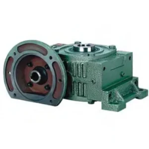
The FO Series Double Worm Gear Reducer covers 80:1 to 180:1 reduction with two distinctions from the through-shaft FA: an IEC B5 motor flange that eliminates the input coupling, and a hollow bore output that eliminates the output coupling. Zero couplings at both drivetrain ends. Any IEC B5 motor bolts directly to the input face; the driven shaft seats directly in the keyed bore. Six sizes (80-175) cover Ø32-65 mm bores and 8-18 rpm output from a standard 4-pole motor running at rated speed and full fan cooling. For Australian shaft-mount drives requiring 80:1-180:1 with motor-direct IEC connection and no coupling hardware, the FO is the complete single-unit specification.
Technical Specifications — FO Series Double Worm Gear Reducer
Input: IEC B5 Flange — Motor Direct
Motor bolts to IEC B5 flange. No jaw coupling, no coupling guard, no alignment. E1, E2 (bolt circles) and F (locating diameter) match IEC B5 standard frames for each FO size.
Output: Hollow Bore — No Output Coupling
Driven shaft inserts into keyed bore (S diameter, LS depth). Output coupling and alignment step eliminated. Set screw (FO80-100 smooth loads) or shrink disc (FO120-175, shock/cyclic duty).
Output Speeds at 1,450 rpm Input — 4-Pole Motor, 50 Hz
1/90 → 16.1 rpm
1/100 → 14.5 rpm
1/120 → 12.1 rpm
1/150 → 9.67 rpm
1/180 → 8.06 rpm
| Size | Ratio | A (mm) | AB (mm) | B (mm) | E1 (mm) | E2 (mm) | F (mm) | Input U (mm) | LS (mm) | Bore S (mm) | Key W×Y |
|---|---|---|---|---|---|---|---|---|---|---|---|
| 80 | 80-180:1 | 317 | 213 | 210 | 130 | 150 | 140 | 15 | 65 | Ø32 | 10×4.5 |
| 100 | 80-180:1 | 390 | 258 | 245 | 155 | 180 | 190 | 18 | 75 | Ø38 | 10×4.5 |
| 120 | 80-180:1 | 437 | 282 | 285 | 185 | 215 | 220 | 20 | 85 | Ø45 | 12×4.5 |
| 135 | 80-180:1 | 496 | 321 | 320 | 210 | 235 | 260 | 25 | 95 | Ø55 | 15×5 |
| 155 | 80-180:1 | 559 | 367 | 392 | 245 | 295 | 290 | 30 | 110 | Ø60 | 15×5 |
| 175 | 80-180:1 | 630 | 407 | 412 | 267 | 323 | 320 | 35 | 110 | Ø65 | 18×6 |
80:1-180:1
IEC B5 Flange Input
Hollow Bore Output
Self-Locking All Ratios
Zero Couplings Both Ends
FO vs FA — Selecting the Right 80-180:1 Hollow Bore Unit
| Feature | FO | FA |
|---|---|---|
| Input | IEC B5 flange direct | Through-shaft either side |
| Input coupling needed | No | Yes |
| Motor position | Fixed to flange face | Either side flexible |
| Output coupling needed | No | No |
| Best for | New designs, IEC stock | Retrofits, position-constrained |
Choose FO when motor position is determined by the gearbox face — the flange eliminates the input coupling and shortens the installed drivetrain. Choose FA when machine structure constrains the motor position before the gearbox is positioned.
Six Key Engineering Advantages of the FO
IEC Flange Removes Both Input Coupling and Coupling Guard
The IEC B5 flange eliminates the jaw coupling, coupling guard, and input alignment step permanently. Combined with the hollow bore output, the FO removes two rotating coupling bodies from the machine envelope. In Australian AS 4024 machinery safety assessments this can reduce the number of rotating-component hazard zones requiring engineering controls.
Self-Locking at All Ratios — No Motor Brake Required
Both worm stages lock simultaneously at all six FO ratios (80:1-180:1). Driven shaft held against back-drive without brake current or hydraulic pressure on power-off. Eliminates motor brake specification for gate actuators, inclined conveyor positioning, and slow-feed indexing drives at any FO ratio.
Fills the 60:1-200:1 Gap — Motor at Rated Speed Throughout
Standard TEFC motors lose fan cooling below 25 Hz. The FO achieves 8-18 rpm from a motor running at full 50 Hz — no VFD frequency reduction, no forced-cooled motor cost. Full rated motor torque available throughout continuous duty at all six FO ratios.
Better Efficiency Than E-Series at These Ratios
Each FO stage operates at 8:1-14:1 where worm efficiency peaks. Overall FO efficiency at 100:1 is approximately 55-70% versus 50-60% for E-series at its 200:1 minimum. This efficiency advantage reduces heat generation and the thermal management burden in Australian summer ambient above 35 degrees.
Shortest Installed Drive Length — No Coupling Gap at Either End
FO drivetrain: motor flange to FO housing to driven shaft. No coupling hubs, no coupling gaps. Installed length from motor back face to driven shaft shoulder is the shortest achievable at this ratio range — relevant for tight machine bay depth in Australian retrofit and OEM projects.
FO175 — Largest Bore at 80:1-180:1 with IEC Flange Input
FO175 delivers a 65 mm output bore with LS 110 mm engagement depth — covering Australian heavy conveyor head shafts, large mixing shafts, and heavy positioning drives requiring 8-18 rpm with IEC motor direct connection. The only catalogue specification combining Oslash;65 mm bore, flange input, and 80:1-180:1 ratio range.
Application Areas — FO Series Worm Gearbox
- ⛓️ Slow Belt Conveyor Head Shaft — 10-15 rpm Motor Direct (shaft mounted worm gearbox)FO size 100-155 at 100:1-150:1 for slow belt conveyor drives. Motor bolts to IEC flange — no coupling installation, no alignment. Bore mounts on head shaft. Self-locking prevents reverse-travel on inclined conveyors during power-off without motor brake.
- 🌊 Gate Valve and Weir Actuators — IEC Direct in Confined EnclosuresFO100-135 at 120:1-180:1 for gate valve and weir actuators where motor must mount directly to the actuator body without a coupling body in the confined enclosure. IEC motor bolts to FO flange; hollow bore seats on valve stem. Self-locking holds gate position on power-off without hydraulic or electromagnetic braking.
- 🌾 Precision Agricultural Metering — Compact IEC Motor DirectFO80-120 at 80:1-120:1 for precision seeder and fertiliser metering in Australian agricultural equipment. IEC flange mounting makes FO shorter from motor face to driven shaft than any jaw-coupled equivalent. For PTO input variants refer to agricultural PTO shaft resources. For gearbox selection guidance visit gearboxagricultural.com.
- 🧫 Slow Agitator and Mixer Drives — Zero Coupling AssemblyFO80-135 at 80:1-120:1 for paddle mixer and agitator drives in Australian food processing, chemical, and wastewater treatment. IEC flange eliminates coupling from the agitator head; hollow bore mounts directly on the impeller shaft. Self-lock holds impeller stationary during confined space maintenance access.
- 🏭 OEM Positioning and Indexing Drives — IEC Motor Direct Design RequirementFO100-135 at 120:1-180:1 for OEM slow positioning drives specifying IEC motor direct mounting to minimise drivetrain component count. The FO satisfies this at 80:1-180:1 — a ratio range no single-stage flange-input worm reducer can achieve.
Drive Components, Accessories and PTO Integration
IEC Motor — Frame and Shaft Match
Confirm motor IEC frame against FO flange dimensions E1, E2, F and motor shaft diameter against input bore U before ordering. Motor shaft must slide into FO input bore with correct H7/f6 fit. Confirm bore tolerance at design stage — oversized motor shafts require a bushing.
Bore Locking — Set Screw or Shrink Disc
Set screw suits FO80-100 in smooth low-shock service. For FO120-175 or any size in shock, cyclic reversing, or sustained high-torque duty, specify a shrink disc to distribute clamping uniformly over full LS bore depth. Prevents progressive key loosening under cyclic torque at high output torques FO135-175 generates.
Oil — Two Stages, Two Independent Points
Two drain/fill points — one per stage. ISO VG 220 mineral for standard service. PAO synthetic ISO VG 220 at ratios 120:1 and above in Australian ambient above 35 degrees — extends thermal ceiling and service interval to 5,000 hours.
Torque Arm — Bore Reaction Plus Assembly Weight
Shaft-mount torque arm resists bore reaction torque and gravitational moment of motor-plus-FO assembly. At FO155-175 with motor, assembly can exceed 60-100 kg. Calculate gravitational moment at arm anchor distance — for horizontal shaft with motor above the shaft axis this can exceed the reaction torque in the anchor force calculation.
Thermal Verification — Continuous Duty Above 35 Degrees
Two-stage worm still converts 30-45% of input power to heat even at FO efficiency levels. At 150:1 and 180:1 in continuous duty above 40 degrees ambient, verify thermal rating at your input power before finalising size selection. PT100 on second-stage housing recommended for remote actuator and valve installations.
Flange Bolt Torque — IEC Standard Values Required
IEC B5 flange bolts must be torqued to the IEC-specified value for the motor frame. Under-torqued bolts allow micro-movement under vibration, fretting the flange locating rabbet progressively. Re-torque at first 500-hour check and verify at every 2,500-hour service interval.
Maintenance Schedule — FO Series
| Interval | Task | FO-Specific Note |
|---|---|---|
| First 500 hr | Flush both stages; re-torque locking element; flange bolt check | Re-torque IEC flange bolts to IEC-specified value — vibration during run-in commonly relaxes preload below the friction-hold threshold before the first planned service |
| 2,500 hr | Oil change both stages; all seals; flange gasket; locking element | Inspect IEC input bore (U) for fretting oxide — under-torqued flange bolts during installation allow micro-movement that accumulates as progressive bore fretting at the key interface |
| 5,000 hr | Remove bore; bore and inter-stage bearing inspection | Measure output bore diameter — sustained high torques at 80:1-100:1 in large FO sizes can progressively widen the bore; confirm within 0.05 mm of nominal before reinstalling the driven shaft |
For FO size selection, IEC motor frame confirmation, thermal rating at your duty cycle and Australian ambient, shrink disc specification, and torque arm calculation, contact our engineering team at worm-gearbox.top. Submit your enquiry via the contacts page.