Description
Technical Specifications — WDKA & WDKS Series
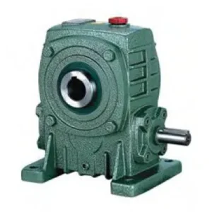
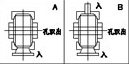
WDKA — Deep Bore (WA-class)
IEC B5 flange input. WA-class hollow bore depth (HL = 150 mm at size 100). Ball bearings throughout. Correct for shock service factors up to 2.0. Sizes 40–175.
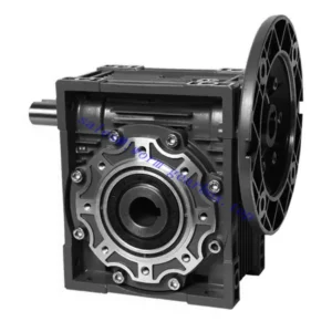
WDKS — Deep Bore + Tapered Rollers (WS-class)
IEC B5 flange input. WS-class bore depth. Tapered roller output bearings from size 80 — handles sustained axial thrust. Correct for shock SF ≥ 2.0 and combined radial + axial loading. Sizes 40–175.
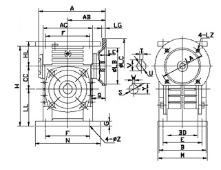
| Size | Power (kW) | Ratio | A (mm) | B (mm) | H (mm) | WDKA HL (mm) | LL (mm) | Flange LZ (mm) | Input Q (mm) | Output Bore S | Weight (kg) |
|---|---|---|---|---|---|---|---|---|---|---|---|
| 40 | 0.12 | 1/10–1/60 | 138 | 90 | 135 | 45 | 60 | 140 | 25 | Ø20 | 5 |
| 50 | 0.18 | 1/10–1/60 | 155 | 107 | 165 | 50 | 80 | 140 | 25 | Ø20 | 8.5 |
| 60 | 0.37 | 1/10–1/60 | 170 | 117 | 195 | 60 | 93 | 160 | 35 | Ø25 | 11 |
| 70 | 0.37/0.75 | 1/10–1/60 | 206 | 131 | 233 | 73 | 108 | 160/200 | 35/45 | Ø30 | 17 |
| 80 | 0.75/1.5 | 1/10–1/60 | 232 | 144 | 268 | 83 | 123 | 200 | 45 | Ø35 | 26 |
| 100 | 1.5 | 1/10–1/60 | 266 | 175 | 330 | 150 | 190 | 200 | 55 | Ø40 | 39 |
| 120 | 2.2/3.0 | 1/10–1/60 | 340 | 200 | 395 | 180 | 230 | 250 | 65 | Ø45 | 60 |
| 135 | 3.0/4.0 | 1/10–1/60 | 375 | 212 | 455 | 215 | 250 | 250 | 65 | Ø60 | 88 |
| 155 | 5.5 | 1/10–1/60 | 442 | 312 | 493 | 235 | 280 | 300 | 85 | Ø70 | 120 |
| 175 | 7.5 | 1/10–1/60 | 465 | 334 | 558 | 260 | 310 | 300 | 85 | Ø80 | 160 |
⚠️ WDKS — Tapered Roller Output Bearings (Size 80 and Above)
The WDKS replaces deep-groove ball bearings at the output bore with tapered roller bearings from size 80 onwards. Tapered rollers carry both radial and axial shaft loads simultaneously — this is the defining capability that separates the WDKS from the WDKA. Specify the WDKS whenever the driven shaft generates sustained axial thrust: screw conveyor helical flight force, belt drive misalignment, inclined chain drive overhung load with axial component, or any helical-cut driven element.
0.12–7.5 kW
IEC B5 Flange Input
Deep Hollow Bore
WDKS: Tapered Rollers Size 80+
Shock Rated SF ≥ 2.0
Why Bore Depth Is the Critical Variable Under Shock Conditions
The WDKA and WDK carry the same bore diameter at each size number. The engineering difference is entirely in HL — the bore contact length. At size 100: WDKA HL = 150 mm versus WDK HL = 80 mm. This 88% increase in contact length changes three measurable outcomes under load:
📉 Key Face Pressure — Halved
At the same output torque, WDKA key face pressure ≈ 53% of WDK key face pressure. Fretting fatigue initiates when surface pressure exceeds the material’s threshold — the WDKA sustains shock torques that push well past the WDK’s fretting limit without initiating surface damage.
🔬 Micro-Slip Amplitude — Reduced
The elastic deformation of bore and shaft under load generates micro-slip at the contact surface. A longer bore distributes this deformation over more contact length, reducing micro-slip amplitude per unit — the direct mechanism that delays fretting corrosion onset in cyclic and shock-load service.
⚖️ Static Self-Locking Distribution
At ratios ≥ 30:1, the holding torque acts through the bore-shaft key connection. The WDKA’s longer key engagement distributes static load over proportionally more face area — reducing bore fretting under sustained gravity loads in vertical shaft applications and loaded gate actuators.
WDKA / WDKS: Six Key Advantages for Demanding Australian Applications
WA / WS-Class Bore Depth — Shock Tolerance
WDKA HL = 150 mm at size 100; WDKS matches this with added tapered roller support. Stone strikes on auger shafts, conveyor jam events, and emergency motor stops impose 3–5× rated torque transiently. The deep bore distributes this over sufficient key face area to prevent fretting initiation in conditions that consume WDK keyways within a single harvest season.
IEC Flange Input — Zero Input Coupling
The IEC B5 flange input eliminates the motor-to-reducer coupling entirely. In shock-load environments, jaw couplings regularly require spider replacement every 6–12 months — the WDKA/WDKS removes this maintenance item from the schedule permanently. Motor concentricity is factory-set to 0.05 mm TIR by the machined flange datum.
WDKS: Axial Thrust Capacity (Tapered Rollers)
Deep-groove ball bearings resist radial load only — sustained axial shaft thrust from screw conveyor flights or helical-cut driven elements overloads them rapidly. WDKS tapered roller output bearings at size 80+ carry both radial and axial load simultaneously as a rated condition. This eliminates the bearing failure mode that is the primary cause of premature hollow-bore reducer failure on screw conveyors across Australian bulk handling installations.
Size 40 — Smallest W-Family Shock-Rated IEC Unit
Size 40 at 0.12 kW is unique to the WDKA/WDKS within the WD range — no WDK size 40 exists. For small-frame shaft-mounted applications where IEC motor flange input and deep bore engagement are both required in a compact package, size 40 fills a gap that no other single unit in the W-family range covers.
W-Series Housing — Retrofit Without Structural Work
Upgrading a WDK that is showing early fretting signs to a WDKA at the same size number requires no baseplate modification — external housing dimensions match. The driven shaft bore diameter is the same; only the bore depth and bearing arrangement change. This is the correct specification upgrade path when shock loads intensify on existing W-series machines.
Self-Locking with Deep Bore Static Retention
At ratios ≥ 30:1, self-locking holds the output bore on power-off. The WDKA/WDKS deep bore distributes this static holding torque over 88% more key face area than the WDK — critical for applications where the driven shaft carries a sustained gravity load (loaded hoists, inclined conveyors, gate spindles) during the lock-up period between power-off and the next start.
Applications — Environments Where WDK Fretting Begins and WDKA/WDKS Does Not
- 🌾 Grain Auger Shaft Drives — Stone Strike Resilience
WDKA size 100–135 at 30:1–40:1 bore-mounts on grain auger shafts of Ø40–60 mm. Stone-strike shock events generate 3–5× rated torque transiently. The WDKA bore depth (HL 150–215 mm at these sizes) distributes this over sufficient key face area to prevent fretting. The IEC motor flange eliminates the input jaw coupling — removing the coupling spider that, in normal service, requires replacement every 6–12 months on shock-loaded auger drives in Australian broadacre grain operations. - 🔩 Screw Conveyors — Axial Thrust + Shock (WDKS) (high torque worm gearbox)
WDKS size 80–135 for mineral, fertiliser, and grain screw conveyor head shaft drives. Screw flights generate sustained axial thrust proportional to material column pressure — ball bearings fail within months under this load on screw conveyors. The WDKS tapered roller output bearings handle this as a rated continuous load. The deep bore handles restart shock from bridged material. Both failure modes resolved simultaneously in one specification. - ⛏️ Mining Conveyor Belt Drives — Emergency Stop Shock
WDKA/WDKS size 120–175 on mining conveyor belt drives where emergency belt stops generate transient torques of 3× rated and sustained belt tension generates axial overhung load at the reducer bore. The WDKS handles both simultaneously. The IEC flange input eliminates the input coupling that would otherwise generate coupling-gap contamination in the dusty mining environment — a significant seal and contamination advantage on underground conveyor installations. - 🚜 Heavy Agricultural PTO-to-Electric Conversion
Heavy rotary tillers, mulchers, and disc mowers converted from tractor PTO to electric motor drive need WDKA size 80–120 where the implement shaft is large-diameter and direct-on-line motor starting generates startup shock. The IEC flange accommodates any standard electric motor; the deep WDKA bore handles startup torque over sufficient key face length. For PTO shaft integration on partially-converted implement drives, see our resources on agricultural gearbox integration. - 🏗️ Winch and Hoist Drum Drives (AS 1418)
WDKA size 100–155 at 20:1–40:1 for winch drum shaft drives. The deep bore distributes emergency-stop shock torque over 150–235 mm of key face. Self-locking at ratios ≥ 30:1 sustains the static gravity load between power cycles without bore fretting that would progressively loosen the bore connection and compromise the secondary load-holding function — which is a safety-critical failure mode, not just a maintenance issue.
PTO Integration, Drive Accessories, and Component Selection
The WDKA/WDKS is supplied as a standalone reducer unit. The following components are specified separately and are essential to correct application performance:
PTO Adaptor + Friction Slip Clutch
For agricultural drives retaining tractor PTO input, a yoke-end IEC flange adaptor couples the PTO shaft to the WDKA/WDKS input face. A friction slip clutch calibrated at 1.5× rated input torque is mandatory — stone-strike events can generate 8–10× rated torque instantaneously; even the WDKS’s deep bore cannot sustain these events indefinitely without clutch protection as the first line of defence. Refer to PTO shaft and slip clutch specifications for yoke and spline sizing.
IEC Motor — Shock Application Selection
For shock-load applications, select a curved-jaw coupling design or a fluid coupling between the VFD and motor if direct-on-line starting is retained — these limit the peak startup torque transmitted into the WDKA/WDKS worm gear. Alternatively, a VFD with current limiting and soft-start ramp eliminates direct-on-line startup shock entirely and is preferred for WDKA/WDKS drives where controllable starting is feasible.
Shrink Disc — Mandatory for Shock Loads
For all WDKA/WDKS shock-load applications, the bore locking element must be a shrink disc — not a set screw. Uniform radial clamping across the full bore depth (150–260 mm depending on size) prevents the progressive set screw loosening that repeated shock torques cause regardless of bore depth. Specify shrink disc by bore diameter S and required transmissible torque with service factor applied.
Heavy-Duty Torque Arm (Sizes 120+)
WDKA/WDKS sizes 120–175 weigh 60–160 kg with motor. In shaft-mount configuration, the torque arm must carry both the reaction torque from the output bore and the gravitational moment of the motor-plus-reducer assembly. A dual rubber-bushed heavy-duty arm is required at these sizes — specify for combined dynamic and gravitational loading, not reaction torque alone.
PAO Synthetic Oil — Hot Ambient & High Ratio
At ratios 40:1+ in continuous duty in 40°C+ Australian summer ambient, PAO synthetic ISO VG 220 extends the thermal rating by 10–15% and service interval to 5,000 hours. For WDKA/WDKS units on grain or mineral conveyors that operate continuously during harvest campaigns where scheduled oil changes are logistically difficult, the extended synthetic interval is a material operational benefit.
PT100 Thermal Sensor (Sizes 100+)
NPT sensor port fitted at sizes 100+. On enclosed mining and grain handling conveyors where the reducer housing is not visually accessible during operation, a SCADA-connected PT100 provides overtemperature protection and trend data. Worm gear thermal failure in a bore-mounted unit at size 155 or 175 is a significant unplanned downtime event — monitoring is proportionally more valuable at larger frame sizes.
WDKA vs WDKS — The Selection Decision in Practice
| Load Condition | Specify WDKA | Specify WDKS |
|---|---|---|
| Smooth continuous load, no shaft thrust | — | — |
| Shock loads (SF 1.5–2.5), no axial thrust | ✓ | Also acceptable |
| Sustained axial shaft thrust (screw conveyor, helical drive) | Not recommended | ✓ |
| Combined shock AND axial thrust | Not recommended | ✓ |
| High shock (SF > 2.5) — stone strikes, jam events | ✓ + shrink disc | ✓ + shrink disc |
| Vertical shaft, sustained gravity load at bore | ✓ preferred | Also acceptable |
Maintenance Schedule — WDKA & WDKS
| Interval | Task | WDKA/WDKS Note |
|---|---|---|
| First 500 hr | Oil flush; shrink disc cross re-torque; flange bolt check | No fretting expected at deep bore under correct locking force — any rust-brown oxide at bore faces within first 500 hours indicates inadequate shrink disc torque; re-torque to full specification immediately |
| Every 2,500 hr | Full oil change; all seals; shrink disc bolts; flange bolts; WDKS tapered roller pre-load check | WDKS: verify tapered roller axial pre-load within specification — zero axial play with <0.05 mm pre-load. Pre-load loss indicates bearing wear; adjust shims before bearing failure propagates to bore fretting |
| Every 5,000 hr | Remove bore; bore contact and shaft inspection; all bearing play measurement | WDKS: inspect tapered roller cage and raceway for pitting or spalling — replace bearings as a matched set, not individually; re-set pre-load after replacement to the specified shim value |
| After any jam event | Full internal inspection before return to service | Even deep bore cannot sustain unprotected 8–10× rated shock events — inspect worm wheel bronze surface for step loading wear pattern before resuming; do not return to service on visual inspection alone |
For WDKA versus WDKS selection guidance, service factor calculation, shrink disc specification, tapered roller pre-load data, and project procurement scheduling for sizes 40–175, the engineering team at our worm gearbox technical portal provides application-specific analysis. Submit your driven shaft diameter, shock load profile, axial thrust estimate, and ambient temperature for a confirmed size and variant recommendation. Ready to specify? Contact us via the technical enquiry page.