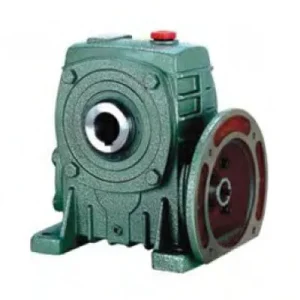
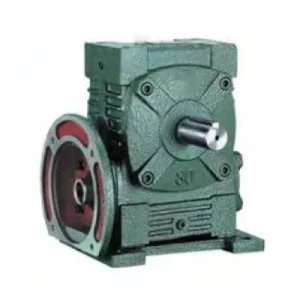
Description
Technical Specifications — WDKO Series Worm Gear Reducer
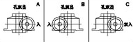
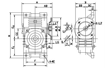
Configuration: IEC B5 Flange Input + Dual Co-Axial Hollow Bore Output
One motor drives two co-axial output bores simultaneously from a single worm wheel — exact synchronisation, no phase error. Both bores exit from opposite housing faces on the same axis. Rated output torque is the combined total across both bores; select accordingly.
| Size | Power (kW) | Ratio | A (mm) | B (mm) | BC (bore ctrs, mm) | CC (mm) | E1 (mm) | Flange LZ (mm) | Input Q (mm) | Output Bore S | Weight (kg) |
|---|---|---|---|---|---|---|---|---|---|---|---|
| 40 | 0.12 | 1/10–1/60 | 138 | 90 | 45 | 40 | 72 | 140 | 25 | Ø20 × 2 | 5 |
| 50 | 0.18 | 1/10–1/60 | 155 | 107 | 53.5 | 50 | 90 | 140 | 25 | Ø20 × 2 | 8.5 |
| 60 | 0.37 | 1/10–1/60 | 170 | 117 | 58.5 | 60 | 102 | 160 | 35 | Ø25 × 2 | 12 |
| 70 | 0.37/0.75 | 1/10–1/60 | 206 | 131 | 65.5 | 70 | 120 | 160/200 | 35/45 | Ø30 × 2 | 18 |
| 80 | 0.75/1.5 | 1/10–1/60 | 232 | 144 | 72.2 | 80 | 140 | 200 | 45 | Ø35 × 2 | 26 |
| 100 | 1.5 | 1/10–1/60 | 266 | 175 | 87.5 | 100 | 165 | 200 | 55 | Ø40 × 2 | 39 |
| 120 | 2.2/3.0 | 1/10–1/60 | 340 | 200 | 100 | 120 | 195 | 250 | 65 | Ø45 × 2 | 61 |
| 135 | 3.0/4.0 | 1/10–1/60 | 375 | 212 | 110 | 135 | 230 | 250 | 65 | Ø60 × 2 | 88 |
| 155 | 5.5 | 1/10–1/60 | 442 | 312 | 140 | 155 | 250 | 300 | 85 | Ø70 × 2 | 124 |
| 175 | 7.5 | 1/10–1/60 | 465 | 334 | 150 | 175 | 273 | 300 | 85 | Ø80 × 2 | 158 |
⚠️ Critical: Rated Torque Is the Combined Total Across Both Bores
Both WDKO output bores share one worm wheel. The catalogue rated output torque is the combined total from both bores simultaneously. If each driven shaft requires T (Nm), select a WDKO rated for 2T combined. Treating the rated torque as per-bore capacity results in 2× overload on the worm wheel — the most common WDKO specification error in Australian project engineering.
0.12–7.5 kW
IEC B5 Flange Input
Dual Co-Axial Hollow Bores
Exact Synchronisation — 1:1
Zero Couplings All Three Ends
How the Co-Axial Dual Bore Configuration Works
The WDKO drives both output bores from a single worm wheel positioned centrally in the housing. The wheel’s bore extends through both housing faces — the two driven shafts insert from opposite sides into this common bore. The speed relationship between the two output shafts is exactly 1:1 with zero phase error, determined by the single worm wheel they share, not by any chain, belt, or gear linkage between them.
🔄 Co-Axial vs 90° Dual Output (WDKX)
WDKO: both output shafts on the same rotational axis, exiting opposite housing faces. WDKX: one bore on the primary axis, the second exits at 90° via an internal bevel gear. WDKO is mechanically simpler (no bevel stage), more efficient, and correct for in-line synchronised drives. WDKX is correct for L-shaped twin-drive layouts requiring perpendicular output without an external bevel stage.
⚖️ Speed Accuracy — Why 1 Worm Wheel Matters
Synchronising two separate reducers with a chain achieves approximately 1:1 speed ratio — but accumulates error from chain stretch, sprocket tooth wear, and chain tension fluctuation over time. The WDKO’s single-wheel geometry delivers factory-exact 1:1 ratio permanently. In twin-auger grain conveyors, this prevents the differential auger velocity that causes grain bridging and uneven throughput as a chain-drive system wears.
🔌 Three-End Zero Coupling — The Integration Case
The WDKO eliminates couplings at all three connection points: input (IEC flange — no jaw coupling), output bore 1 (shaft slides into bore — no coupling), output bore 2 (same). Three couplings, three guards, three alignment procedures removed simultaneously. In food processing and enclosed machine designs, this also removes three rotating-component hazard zones from the safety assessment.
Six Reasons the WDKO Outperforms Separate Reducer Pairs
Permanent Exact Synchronisation
Both bores share one worm wheel — speed ratio is exactly 1:1 from day one to end of service life. There is no mechanical mechanism that allows speed drift between the two output shafts. Chain-coupled separate reducer pairs drift as chain stretch progresses; the WDKO cannot drift by design.
Motor Direct — IEC Flange Eliminates Input Coupling
The IEC B5 flange eliminates the input jaw coupling, coupling guard, motor base, and alignment procedure on the input side. Any IEC B5 frame motor bolts directly — no custom motor bracket, no alignment jig. Motor concentricity is factory-set at 0.05 mm TIR by the machined flange datum; there is no alignment step for the technician to perform or misperform.
Replaces Two Reducer + Two Motor Sets
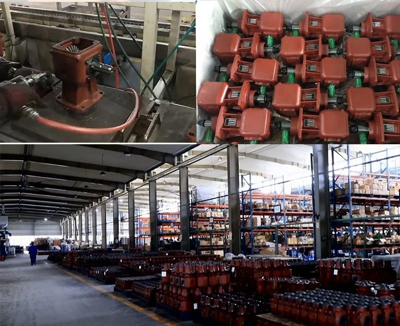
One WDKO replaces two separate motor-reducer-VFD-coupling sets for synchronised twin drives. The total hardware reduction: two reducers → one, two motors → one, two VFDs → one, four couplings → zero, four coupling guards → zero. In high-volume OEM production the per-unit cost and assembly time reduction is substantial; in maintenance-intensive environments the reduced part count halves the scheduled maintenance scope.
Self-Locking Holds Both Bores Simultaneously
At ratios ≥ 30:1, both output bores hold stationary on power-off simultaneously without a brake — both driven shafts are locked by the same self-locking worm mesh. In twin-auger grain handling systems loaded with full grain column at shutdown, both shafts are restrained against grain pressure simultaneously and symmetrically, preventing the grain-bridging asymmetry that results from one shaft being braked while the other creeps.
W-Series Footprint — Legacy Machine Retrofit
The WDKO housing external dimensions follow the W-series convention — the same foot pad bolt pattern, A-dimension, and H-dimension as the W-series baseline. Retrofitting from a W-series solid-shaft unit to a WDKO twin-drive unit in the same machine bay requires no structural modification. The second output bore adds only the axial housing length at the rear face, not the overall machine bay width.
Single VFD Controls Both Output Speeds
One motor, one VFD. Both output bore speeds change proportionally when the VFD frequency changes — the speed ratio between them remains exactly 1:1 at all frequencies. Separately-controlled dual-reducer systems require synchronisation logic between two VFDs; any control system lag introduces a speed differential. The WDKO makes this synchronisation problem physically impossible rather than algorithmically managed.
Applications — Where the WDKO Eliminates Synchronisation Engineering Entirely
- 🌾 Twin-Auger Grain Handling Systems — Zero Drift Synchronisation (worm gear drive)
WDKO size 100–135 at 30:1–40:1 drives matched twin grain augers from a single IEC motor. Both augers receive identical speed permanently — chain-couple drift that causes uneven grain flow is eliminated. In Australian bulk grain intake pits where the combined throughput of both augers is the site’s bottleneck, maintaining both augers at exactly matched speed throughout the season has measurable throughput implications. The IEC flange input also removes the input coupling that accumulates grain chaff in the coupling recess during outdoor harvest operations. - 🍶 Fermentation Tank Twin Paddle Drives
WDKO size 80–120 drives opposing paddles entering a fermentation or mixing vessel from both sides simultaneously. Both paddles receive exactly matched speed and torque — critical for uniform mixing without flow bias toward one side. The IEC flange mounts directly on the vessel lid or frame; no input coupling body protrudes into the headspace above the vessel. The hollow bore at both ends means no shaft stub or coupling guard extends into the tank environment that requires sanitary compliance. - 📦 Packaging Machine Infeed/Outfeed Conveyor Pairs
WDKO size 60–80 at 20:1–30:1 drives matched infeed and outfeed conveyor belts from one motor and one VFD. Both belts maintain exactly matched speed throughout the VFD frequency range — no slip differential between conveyors that would cause package accumulation at the transfer point. Total drive system: one WDKO, one motor, one VFD, one PLC output channel. Alternative: two motors, two VFDs, two reducers, synchronisation logic, and a PLC output for each with interlock programming. The WDKO eliminates the synchronisation problem at the hardware level. - 🚜 Agricultural Twin-Implement Drive (worm gearbox for agriculture)
WDKO size 80–100 drives a primary implement roller and a matched secondary roller from one motor where both rollers must maintain exact speed for uniform product processing — seed treatment rollers, rubber ring applicators, twin-roller spreaders. The W-series housing fits the implement frame envelope designed around W-series reducers; the dual bore outputs eliminate the drive chain that would otherwise require weekly tension adjustment in field conditions. For implement-level integration with tractor PTO as the input source, PTO shaft connection to the IEC flange face via a yoke adaptor is the standard approach. - 🏭 Industrial Mixer Twin Agitator Drives
WDKO size 100–155 for industrial mixing tanks where two agitator shafts entering from opposite ends of the vessel must rotate at matched speed for uniform batch mixing — polymer reactors, slurry conditioners, pulp mixers. The co-axial bore geometry allows both agitator shafts to be driven from a single overhead drive point without cross-coupling belts or chains across the vessel. Self-locking at ratios ≥ 30:1 holds both shafts stationary during tank loading and unloading without a brake, preventing the inadvertent rotation from agitator-shaft overhang that can cause personal injury during confined space entry for tank cleaning.
Drive Accessories and PTO Integration for the WDKO
PTO Shaft + Flange Adaptor + Slip Clutch
For tractor PTO input, a yoke-end IEC flange adaptor with friction slip clutch (calibrated at 1.5× combined rated input torque) couples the PTO to the WDKO input face. The slip clutch must be set to the combined input torque threshold — when one output bore jams, full motor/PTO torque concentrates on the jammed bore until the slip clutch trips. Setting the clutch to per-bore torque instead of combined input torque leaves the jammed bore unprotected.
IEC Motor — Combined Torque Sizing
Motor power must cover the combined torque demand of both output bores divided by the ratio and efficiency. If each driven shaft requires T₁ and T₂ (Nm), required input power = (T₁ + T₂) / (ratio × η). Using only one bore’s torque for motor sizing results in an undersized motor that trips on thermal overload during steady-state combined operation — the most common WDKO commissioning error.
Dual Shrink Discs — Both Bores
Both output bores require individual locking elements. For all non-smooth continuous applications, specify shrink discs for both bores — uniform radial clamping over each bore depth prevents progressive set screw loosening from cyclic or shock torques. Torque both shrink discs in the same cross-pattern sequence to maintain equal clamping force distribution across both bore faces simultaneously.
Torque Arm — Combined Load Calculation
The WDKO torque arm must resist the combined reaction torque from both output bores (T₁ + T₂) plus the gravitational weight moment of the motor-plus-reducer assembly. This is larger than an equivalent single-bore reducer — always recalculate when specifying the torque arm. The WDKO’s additional rear housing section (to accommodate the second bore) also shifts the centre of gravity rearward compared to a single-bore WDK.
Oil Orientation — Extended Housing
The WDKO housing is longer in the bore-axis direction than the equivalent WDK. In non-standard orientations (bore axis vertical, or bore-axis horizontal with motor shaft vertical), verify oil fill level for the installed orientation — the extended housing shifts the oil-level reference point compared to the WDK standard orientation. Submit your installed orientation to the technical team for orientation-specific fill level confirmation at sizes 100+.
Pressure-Equalising Breather
The WDKO has four shaft penetrations: two bore seal faces and one IEC flange bore — all potential oil-weep points under positive housing pressure. A pressure-equalising breather prevents the positive housing pressure that builds during extended continuous duty from driving oil past any of these seal faces. Fit a breather regardless of the operating duty cycle at sizes 80 and above.
WDKO Installation — The Combined Torque Calculation First
Calculate Combined Output Torque
Before selecting a size: T₁ + T₂ = combined output torque reference. Apply individual service factors per driven load: T₁_SF and T₂_SF may differ if load profiles differ. Sum them: T_combined = T₁_SF + T₂_SF. Select WDKO where rated output torque ≥ T_combined at the chosen ratio. This calculation is non-optional — treating rated torque as per-bore is a specification error.
Verify Thermal Rating at Combined Load
Calculate input power from: P_input = T_combined / (ratio × η). Apply your actual ambient temperature. At ratios ≥ 30:1, the thermal rating is often the governing constraint — not the mechanical torque rating. In 40°C+ Australian ambient, verify thermal rating with PAO synthetic oil specification if the calculated input power approaches the thermal limit.
Verify Both Bore Diameters and Lengths
Both output shaft diameters must equal the WDKO bore S dimension. If the two driven shafts have different diameters, the WDKO cannot accommodate them — confirm both shaft diameters are identical before specifying. If they differ, an adaptor sleeve or custom bore sizing is required; contact the technical team.
Mount and Lock Both Bores Simultaneously
Slide both driven shafts into their respective bores simultaneously — inserting one fully while the other is disengaged can cause the worm wheel to shift axially and misalign the seal between the bore face and housing. Fit and torque both shrink discs in sequence before applying any load to either bore.
Bolt Motor to IEC Flange
Insert motor shaft into input bore Q. Confirm motor shaft does not contact bore bottom before motor face is flush with flange face. Torque all flange bolts in a star pattern to specified grade torque. No alignment procedure required — concentricity is set by the machined flange datum. Fit pressure-equalising breather at this stage.
Commission Under Combined Load — Both Bores Active
Run under combined load from first commissioning — do not test with only one bore connected. Single-bore operation generates an asymmetric radial load on the worm wheel that can cause premature bearing wear not visible in the first operating hours. The WDKO is designed for simultaneous dual-bore loading; single-bore testing does not represent the unit’s actual duty condition.
Maintenance Schedule — WDKO Dual-Bore Configuration
| Interval | Task | WDKO Dual-Bore Note |
|---|---|---|
| First 500 hr | Oil flush; both shrink discs cross re-torque; flange bolt check | Inspect both bore faces for fretting — asymmetric fretting between bore 1 and bore 2 indicates unequal locking force; re-torque the weaker disc to match the properly-locked bore |
| Every 2,500 hr | Full oil change; all seals; both shrink discs; flange bolts; breather check | Inspect both bore seals and the IEC flange face gasket — three oil containment points vs one on a single-bore unit; replace any weeping seal immediately as oil loss in a dual-bore unit is approximately twice the single-bore rate |
| Every 5,000 hr | Remove both bores; full inspection of both bore zones; bearing radial play | Compare bore diameter and concentricity of both bores — unequal wear between bore 1 and bore 2 can indicate unequal load sharing from an underlying application issue, not just locking element variation |
| If one bore jams | Full worm wheel inspection before return to service; inspect both bores | Full motor torque concentrates on the jammed bore and transfers through the worm wheel — even if the jam clears quickly, inspect both bore zones and the worm wheel bronze surface before resuming combined-bore operation |
For WDKO combined torque calculations, IEC motor sizing for dual-bore operation, shrink disc pairing, torque arm combined-load design, and oil orientation verification for non-standard installations, the engineering team at our worm gearbox technical portal provides application-specific support. Submit your two driven shaft diameters, per-shaft torque requirements, service factors, and ambient temperature for a confirmed WDKO size recommendation. For agricultural implement integration questions, contact us via the technical enquiry page.