Description
Technical Specifications
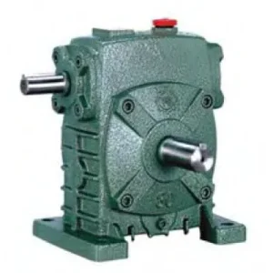
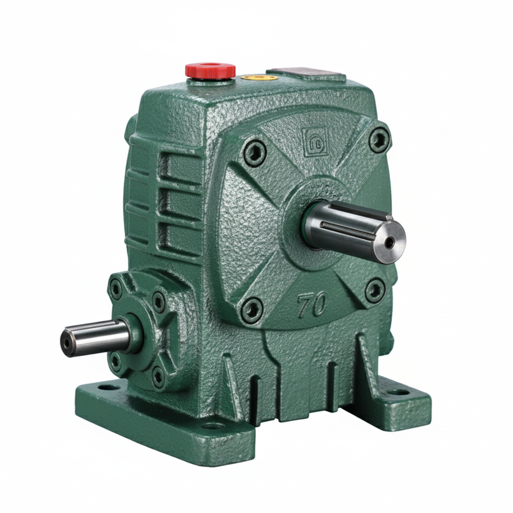
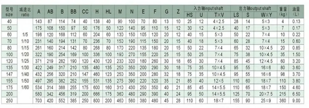
The WPA series worm gear reducer spans sizes 40 through 250, delivering a broad operating envelope for light-duty positioning through sustained heavy-load torque applications. All dimensional tolerances follow national standards; shaft extensions and keyways are interchangeable with NEMA motor frames.
| Parameter | Range / Value | Notes |
|---|---|---|
| Frame Sizes | 40 – 250 | 12 standard sizes |
| Gear Ratio | 5:1 – 60:1 | Single stage |
| Input Power | 0.06 – 15 kW | Motor-dependent |
| Output Torque | Up to 2,800 N·m | Size 250 |
| Input Speed | ≤ 1,500 rpm | Standard design |
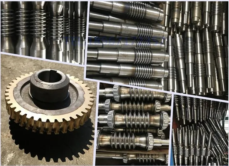
| Worm Material | 45# Steel (HT) | Induction hardened |
| Wheel Material | Tin Bronze | ZCuSn10Pb1 |
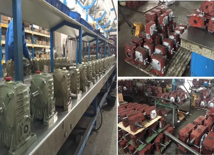
| Housing Material | Cast Iron HT200 | Professionally cleaned |
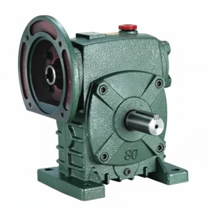
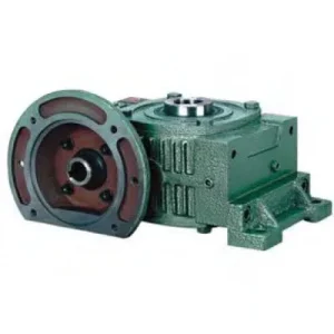
| Mounting Options | Foot / Flange / Shaft | Configurable |
| Lubrication | Oil bath | ISO VG 220/320 |
| Ambient Temp. | −10 °C to +40 °C | Standard range |
| Certifications | ISO 9001 / CE / SGS | Quality assured |
Why the WPA Design Outperforms Generic Reducers

The WPA worm gear reducer occupies a compelling position in the market: a proven architecture refined over decades of industrial use, yet manufactured with material grades and surface finishing standards that place it well ahead of commodity units. The 45# high-quality steel worm undergoes induction hardening before precision grinding, achieving surface hardness levels above 56 HRC — critical for resisting the adhesive wear patterns that destroy softer worms in abrasive environments like cement milling or grain handling.
The tin bronze worm wheel (ZCuSn10Pb1 alloy) provides a sacrificial yet long-lasting counterface. Bronze’s natural affinity for lubrication film retention means the contact patch maintains a hydrodynamic wedge at operating speeds well below the theoretical minimum, reducing boundary-friction heat generation that causes premature housing distortion in cast iron bodies.
The HT200 grey cast iron housing is processed through a dedicated washing line that removes machining swarf to sub-10 µm contamination levels, preventing abrasive particle circulation that would otherwise score the oil seal lips and reduce seal service life to a fraction of its design value.
High Reduction Ratio
Single-stage ratios from 5:1 to 60:1 — no compound stage required for most mid-speed applications.
Self-Locking Capability
At ratios ≥30:1, the lead angle geometry provides inherent back-drive resistance — eliminating external brakes in lifting and positioning setups.
Low Vibration & Noise
Worm–wheel sliding contact naturally damps shock loads, making the WPA suitable for food processing and packaging where noise is a compliance issue.
Compact Right-Angle Layout
90° shaft configuration reduces machine frame size versus in-line solutions, a key advantage in congested conveyor and mixer installations.
How the Worm & Wheel Interaction Determines Drive Performance
The core mechanical principle of the self-locking worm gearbox relies on the geometry of the worm thread and the worm wheel tooth. When the lead angle (the helix angle of the worm thread) falls below the friction angle, the tangential force component at the contact patch cannot overcome friction regardless of the torque applied to the output shaft — this is the origin of the inherent braking behaviour that makes worm drives indispensable in gate actuators, lifting platforms, and angular positioning tables.
The WPA’s worm tooth form is a ZA-profile (Archimedean), offering straightforward re-grinding with standard tool geometry. The worm wheel is cut with a hob whose pitch diameter and profile exactly match the finished worm geometry, producing a conjugate contact pattern that spans up to 30% of the wheel tooth width at rated torque — significantly wider than the nominal line contact seen in inferior manufacturing practices.
Thermal Management Considerations
Sliding contact between the worm and wheel generates more friction heat per kilowatt transmitted than a comparable helical stage. The HT200 housing acts as a passive heat exchanger; at ambient temperatures common across Australian industrial environments, convective cooling from the ribbed exterior maintains oil sump temperatures below 80 °C up to the rated thermal power. For duty cycles above 80% or ambient temperatures exceeding 35 °C, external fan cooling or a water jacket extension can be fitted to maintain oil viscosity within the design window.
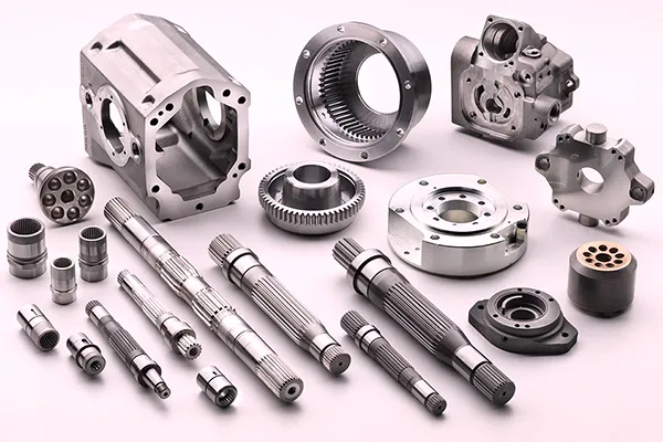
Core Components, Accessories & Mating Parts
Understanding the sub-assembly structure of the WPA helps maintenance teams predict failure modes and plan proactive overhauls. The following component breakdown covers every element involved in force transmission, sealing, and housing integrity.
Worm Shaft (45# Hardened Steel)
The worm shaft is the primary wear element. Manufactured from 45# high-carbon steel, hardened to 56–62 HRC, and ground to an Ra ≤0.8 µm thread surface. The shaft extends on the input side to accept standard motor couplings, NEMA C-face flanges, or hollow-bore adaptors. Keyway slots comply with DIN 6885 Part 1 for universal coupling compatibility.
Worm Wheel (Tin Bronze ZCuSn10Pb1)
The bronze worm wheel is hobbed to achieve a full conjugate tooth profile matching the worm geometry. Tin content at 10% provides tensile strength above 200 MPa while maintaining the ductility necessary to absorb minor shock loads without cracking. For sizes 40–100, the wheel is a solid casting; sizes 120–250 use a centre hub with replaceable bronze rim to reduce replacement cost.
HT200 Cast Iron Housing
Grey cast iron with tensile strength ≥200 MPa absorbs vibration and provides excellent dimensional stability over thermal cycles. External ribs maximise surface area for convective cooling. The interior is shot-blasted and flushed before assembly to eliminate casting sand and machining debris, preventing contamination-induced oil degradation.
Deep-Groove Ball Bearings (Output) + Taper Roller (Input Option)
The standard configuration uses preloaded deep-groove ball bearings on both shafts. For heavy overhung load applications — common in chain sprocket or belt pulley drives — taper roller bearings on the output shaft handle combined radial and axial forces, extending service life beyond 30,000 hours at rated load.
Rotary Shaft Seals & Breather Plug
Double-lip oil seals on both shafts prevent ingress of dust and moisture and retain gear oil. A vented breather plug equalises internal pressure during thermal cycling, preventing positive pressure from forcing oil past the lip seals — a common failure mode in sealed gearboxes that lack adequate venting.
Optional Accessories
Available add-ons include: flange adaptor plates for IEC / NEMA motor frames, hollow shaft output with shrink-disc clamping, extended horizontal base plates for floor mounting, solid-shaft extension couplings, and torque-arm brackets for shaft-mounted operation. Input speed adaptors for dual-motor or gearmotor configurations are available on request.
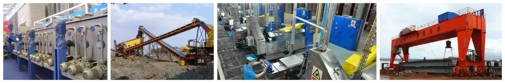
Industrial Applications Across Australia’s Key Sectors
The WPA’s right-angle output shaft and self-locking characteristics make it the default choice in any application where the driven machine must hold position under load without powered braking. Across Australian industry, this translates to demand in five major sectors:
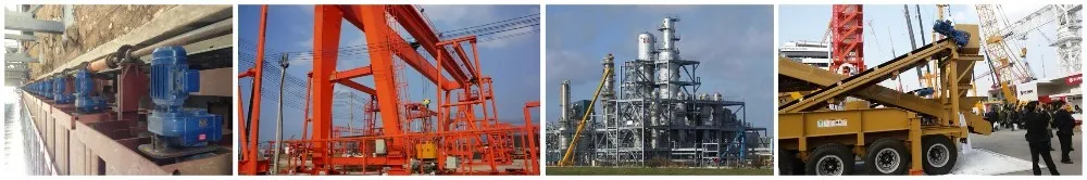
Mining & Quarrying
Conveyor belt drives, feeder screw drives, and cable-reel mechanisms in underground and open-cut mines demand consistent torque delivery under variable load — exactly the operating profile the WPA handles best.
Food & Beverage Processing
The quiet operation and moderate-speed output satisfy hygiene-sensitive environments where vibration damages product quality and noise levels affect operator health standards.
Material Handling
From pallet turntables and roller conveyors to automated storage systems, the WPA provides precise, repeatable positioning without encoder feedback when operated at self-locking ratios.
Agriculture & Irrigation
Gate valve actuators, pivot irrigator drives, and grain auger reducers benefit from the compact profile and robust cast iron construction suited to outdoor Australian conditions. The WPA integrates seamlessly with agricultural gearbox applications across farm machinery systems.
Chemical & Water Treatment
Agitator drives, mixing paddle assemblies, and valve actuators in chemical plants rely on consistent torque at slow speeds — a profile where the WPA’s high-ratio single-stage transmission offers measurable installation cost savings over multi-stage alternatives.
Selecting the Right WPA Frame Size for Your Application
Correct frame size selection involves three primary calculations: required output torque, thermal power rating (which depends on duty cycle and ambient temperature), and bearing life under the actual radial and axial loads imposed by the driven machine. Undersizing the gearbox on any one of these criteria produces premature failure even if the other two parameters are comfortable.
Step-by-Step Selection Process
Calculate the driven shaft speed in rpm and the peak torque in N·m, applying a service factor (1.25–2.0 depending on shock loading class).
With a standard 1,450 rpm motor input, the required ratio equals motor speed ÷ desired output speed. Select the nearest standard ratio from the WPA catalogue (5:1, 10:1, 15:1, 20:1, 30:1, 40:1, 50:1, 60:1).
The thermal power limit is the maximum continuous input power the unit can dissipate without exceeding oil temperature limits. Check the WPA thermal rating table at the actual ambient temperature.
Compare calculated radial and axial loads on both input and output shafts against the catalogue bearing load limits for the chosen frame size.
Choose the appropriate mounting position (foot, flange, shaft mount) and verify that the oil level remains above the worm thread at all orientations to prevent dry running on start-up.
For technical selection assistance or to obtain a detailed WPA dimensional drawing in DXF/STEP format, visit the product catalogue homepage or reach out to the engineering team directly.
Maintenance Schedule & Lubrication Best Practices
The WPA cast iron worm gearbox is designed for oil-bath lubrication with ISO VG 220 gear oil in ambient temperatures up to 25 °C, and ISO VG 320 for continuous operation above 30 °C. The first oil change should occur at 300–500 hours of operation to flush break-in metallic particles; subsequent changes follow a 2,500-hour or 12-month interval, whichever occurs first under normal duty cycles.
300–500 h
First oil change (break-in flush)
2,500 h / 12 mo
Routine oil change interval
< 80 °C
Max continuous oil temperature
Monthly
Visual seal and breather check
Ordering Options, Lead Times & Custom Configurations
Standard WPA units across the complete size range are held in production inventory, enabling rapid dispatch for the most common ratio-and-mounting combinations. Lead times for standard configurations are typically 3–7 business days ex-works; custom shaft diameters, special surface treatments (epoxy paint, hot-dip galvanising), or atypical mounting configurations carry a 2–4 week production lead time.
OEM and wholesale customers purchasing 20 or more units per batch benefit from preferential pricing tiers. Technical drawing review and application engineering support are available at no additional cost for orders requiring non-standard configurations. For enquiries regarding pricing and availability, the engineering team responds within 12 hours during business days.