Description
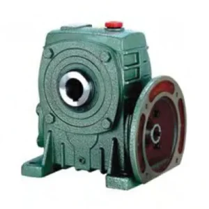
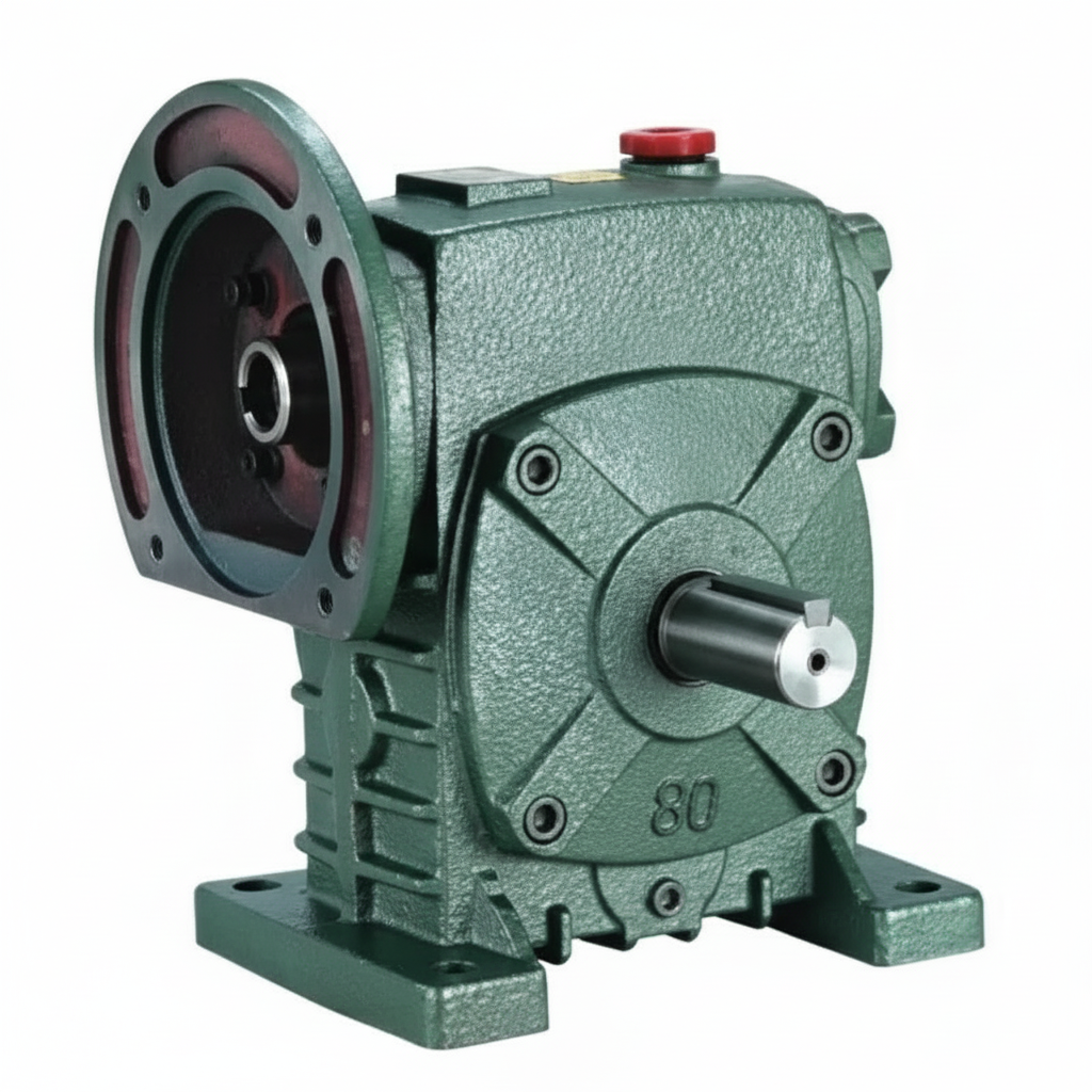
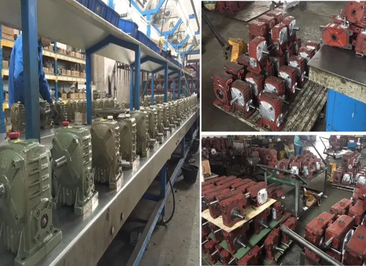
The DS Series Single Standard Worm Gear Reducer — catalogued as WPDS — occupies a specific niche within the WP worm gearbox family that neither the WPS nor the WPDA can fill alone. It combines the extended output shaft geometry and higher overhung load tolerance of the WPS housing with the integrated IEC B5 motor-mounting flange that defines the DA series. The result is a flange mounted worm gearbox that accepts direct motor connection without an intermediate coupling while simultaneously presenting a reinforced output bearing arrangement capable of sustaining the chain and belt radial loads common in Australian conveyor and material-handling plant. Covering sizes 50 through 155 with input powers from 0.18 kW to 5.5 kW and standard gear ratios of 10:1 to 60:1, the WPDS is the specification of choice wherever a motorised worm gear reducer must drive a sprocket, sheave, or gear pinion directly from its output stub.
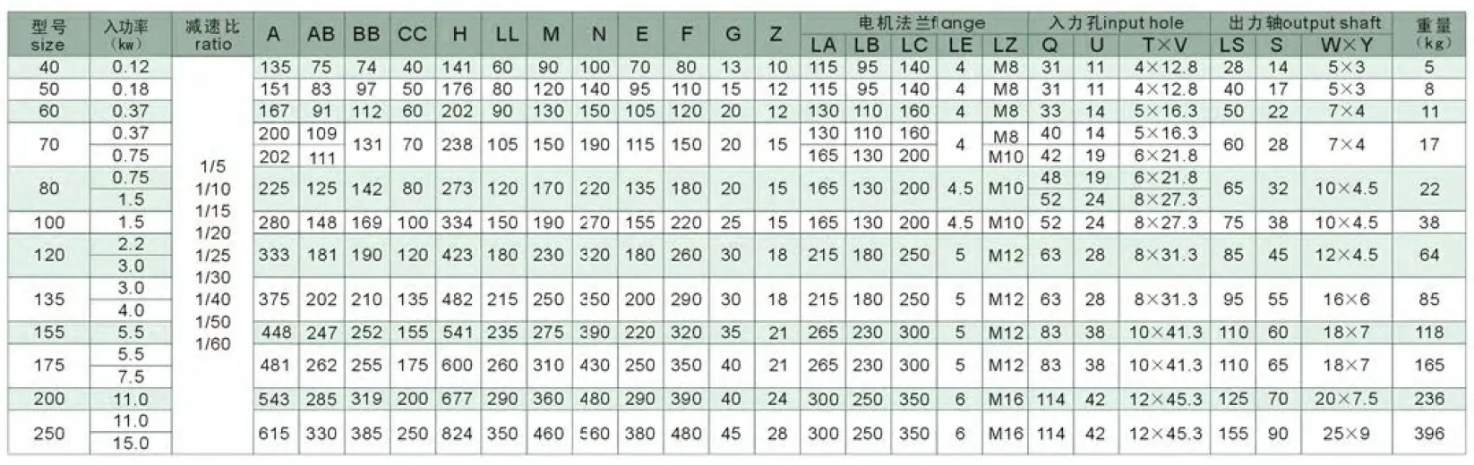
Technical Specifications — DS Series (WPDS) Worm Gear Reducer
| Size | Power (kW) | Ratio | A (mm) | B (mm) | H (mm) | Flange LA (mm) | Output LS (mm) | Weight (kg) |
|---|---|---|---|---|---|---|---|---|
| 50 | 0.18 | 1/10–1/60 | 165 | 175 | 180 | 115 | 40 | 7 |
| 60 | 0.37 | 1/10–1/60 | 185 | 190 | 205 | 130 | 50 | 11 |
| 70 | 0.37 / 0.75 | 1/10–1/60 | 209 | 210–230 | 235 | 130 | 60 | 15 |
| 80 | 0.75 / 1.5 | 1/10–1/60 | 242 | 240 | 265 | 165 | 65 | 23 |
| 100 | 1.5 | 1/10–1/60 | 310 | 255 | 363 | 165 | 75 | 38 |
| 120 | 2.2 / 3.0 | 1/10–1/60 | 361 | 310 | 424 | 215 | 85 | 65 |
| 135 | 3.0 / 4.0 | 1/10–1/60 | 412 | 335 | 481 | 215 | 95 | 84 |
| 155 | 5.5 | 1/10–1/60 | 442 | 402 | 536 | 265 | 110 | 120 |
Input Flange Dimensions — IEC B5 Motor Interface
| Size | Flange Register LZ (mm) | Bolt Circle LB (mm) | Bolt Size | Input Bore Q (mm) |
|---|---|---|---|---|
| 50 | 140 | 95 | M8 | 25 |
| 60 | 160 | 110 | M8 | 35 |
| 70 | 160 / 200 | 110 / 130 | M8 / M10 | 35 / 45 |
| 80 | 200 | 130 | M10 | 45 / 55 |
| 100 | 200 | 130 | M10 | 55 |
| 120 | 250 | 180 | M12 | 65 |
| 135 | 250 | 180 | M12 | 65 |
| 155 | 300 | 230 | M12 | 85 |
0.18 – 5.5 kW
Ratio 10:1 – 60:1
IEC B5 Flange Input
Foot + Flange Mount
WPS-Grade Output OHL
The WPDS Engineering Advantage: Where WPS Geometry Meets DA Integration
The core engineering argument for the WPDS over either the WPS or the WPDA comes down to a single question: does your output shaft carry a significant radial load? If the answer is yes — because a chain sprocket, timing belt sheave, or gear pinion sits on that shaft — then the WPDA’s output bearing arrangement, which mirrors the lighter WPA geometry, may not be adequate. The WPDS solves this by pairing the heavier WPS output shaft and bearing span with the convenience of motor-direct flanging.
Factory-Precision Motor Alignment
Motor shaft and worm shaft share a common machined flange bore, holding concentricity to within 0.05 mm TIR. In separately coupled WPS arrangements, angular misalignment of even 0.1° at the coupling introduces a 2× cyclic radial load on the input bearing at every motor revolution.
WPS-Class Output Overhung Load
The WPDS output shaft diameter and bearing span match the WPS series at every size, not the lighter WPDA geometry. At size 100, the output shaft is 75 mm extension length versus 65 mm on the WPDA — this difference directly multiplies the permissible radial load from sprocket or pulley drives.
Elimination of Input Coupling Failures
Jaw coupling spider degradation is among the most frequent planned maintenance items in Australian food and packaging plant. The WPDS eliminates the coupling entirely, removing this failure mode and the associated safety guarding requirement that Australian WHS regulations mandate for exposed rotating couplings.
IEC Motor Frame Interchangeability
Any IEC B5 motor of the correct frame size mates directly with the WPDS flange. Motor upgrade for power increase or replacement for repair requires no new coupling, no re-boring, and no baseplate modification — a meaningful operational advantage in remote Australian agricultural and processing sites where machine downtime is costly.
Reduced Installed Footprint
Motor flanged directly to the reducer eliminates the motor base, flexible coupling, and coupling guard — reducing the overall drivetrain axial length by 25–40% compared to a WPS with separate motor mounting. This is particularly valuable when retrofitting drives into confined structural bays on older Australian plant.
Self-Locking at High Ratios
At ratios of 30:1 and above, the WPDS worm lead angle falls below the friction angle, making the output shaft effectively non-back-drivable under static conditions. Combined with the direct motor mount, this provides position-holding on shutdown without a mechanical brake — useful in conveyor tail-end drives and gate actuator applications.
Internal Engineering: How the WPDS Housing Handles Both Roles
Housing Casting and Bore Geometry
The WPDS casting integrates three precision-machined features that the WPS alone does not carry: an IEC B5 flange face on the input side, a concentric flange register bore, and a four-bolt circle at the specified LB diameter. These features are machined in a single setup after casting, which is the critical manufacturing step that ensures the motor shaft and worm shaft axes are truly concentric — a standard that cannot be achieved when motor and reducer are separately mounted and aligned in the field. The housing wall thickness on the flange side is increased by 10–15 mm compared to the WPS to accommodate the flange machining without reducing the worm shaft bearing bore wall below minimum structural thickness.
Output Shaft Bearing Span — WPS Standard
Unlike the WPDA, which uses the WPA output shaft geometry, the WPDS carries the WPS-class output shaft with a longer extension and greater shaft diameter at each size. Sizes 80 and above use tapered roller bearings on the output shaft, providing substantially higher permissible radial (overhung) load than the deep-groove ball bearings used in the WPA/WPDA series at the same sizes. The tapered roller arrangement also provides better resistance to axial loads from helical gear or bevel gear auxiliary stages attached to the output shaft, which occur in some multi-stage conveyor drive configurations.
Worm Gear Set — Material and Surface Finish
The worm shaft is 42CrMo4 alloy steel, induction hardened to 58–62 HRC at the tooth surface and cylindrical-ground to Ra ≤ 0.8 µm. The worm wheel is centrifugally cast phosphor-bronze pressed onto a cast iron hub. This material combination gives an initial efficiency of 70–88% depending on ratio, with improvement of 3–5% after the run-in period as the bronze wheel conforms to the worm thread profile. The internal oil volume is sized for splash lubrication at 1,450 rpm rated input; ISO VG 220 mineral gear oil is standard fill, pre-applied before despatch.

Application Environments Where the WPDS Outperforms Alternatives
The WPDS is not a general-purpose substitute for the WPDA. It earns its place in applications where the output shaft must simultaneously sustain a meaningful radial load and the input must accommodate a directly flanged motor. The following represent its strongest application fits across Australian industry:
- ⛓️ Slat and Bucket Conveyor Chain Drives
Size 100–135 WPDS units at 20:1–40:1 ratio drive chain sprockets directly from the output stub — the WPS-class OHL rating prevents the premature bearing failure that occurs when WPDA units are incorrectly specified for the same duty. The direct motor flange eliminates the coupling that is otherwise the weakest point in a conveyor tail-end drive. - 🌾 Agricultural Seed and Fertiliser Metering Drives
Seed metering mechanisms driven by electric motors (rather than PTO shafts) use size 50–70 WPDS units at 40:1–60:1 ratio. The self-locking characteristic holds the metering rotor position when power is removed, preventing over-application on headland turns when the motor is de-energised. - 🏭 Packaging Machine Product Transfer Conveyors
Belt and slat conveyors flanking packaging machines in Australian food plant use size 60–80 WPDS units. The motor-direct format simplifies the electrical panel by eliminating a contactors-protected coupling guard interlock, and the WPS output OHL handles the belt tension side-load without requiring a torque-arm extension bracket. - 💧 Water and Wastewater Treatment Plant Drives
Sludge scraper mechanisms, slow paddle mixers, and chemical dosing augers in municipal water treatment use size 100–155 WPDS units. The sealed housing resists moisture ingress from wash-down and spray in wet areas, and the integrated motor flange suits stainless structural support frames where separate motor bases add unnecessary weight. - 🔄 Material Handling Turntables and Indexers
Pallet turntables and rotary indexing fixtures in Australian automotive and warehousing operations use size 80–120 WPDS units at 30:1–60:1 ratio. The worm self-locking holds the table under load without power, and the direct-mount format keeps the drive envelope within the rotating structure’s weight limit without adding a separate motor base structure. - 🔬 Pharmaceutical and Food-Grade Mixer Drives
Mixing and blending equipment in pharmaceutical manufacturing and dairy processing use size 50–80 WPDS units where the IEC motor frame interchangeability allows standard TEFC motors from any Australian electrical supplier. Stainless output shaft extension and food-grade lubricant (NSF H1) variants are available as non-standard configurations.
PTO Shaft Integration and Associated Drive Components
Although the WPDS is primarily designed for motor-flange input, it is also used in Australian agricultural applications where a PTO shaft assembly drives the reducer through the flange bore. The following components are typically associated with a complete WPDS drivetrain:
IEC Motor (TEFC, B5 Flange)
Standard 4-pole TEFC motors at 1,450 rpm are the normal pairing. Confirm the motor’s D-end flange register and shaft length against the WPDS flange table before ordering — motor shaft length exceeding the WPDS bore depth (T×V dimension) prevents correct flange seating.
PTO Shaft with Flange Adaptor
Where tractor PTO drives the WPDS rather than an electric motor, a telescoping PTO shaft with a flange-end adaptor engages the WPDS input flange bore. The adaptor must be rated for the combined torque of both driven loads and must include a shear bolt or friction slip clutch to protect the worm gear set from implement rock strikes.
Output Shaft Coupling and Guard
The WPDS eliminates the input coupling but the output stub still requires a jaw or disc coupling with a polycarbonate guard to comply with Australian WHS rotating machinery guarding requirements. Size the coupling for the full output torque at the selected ratio, not the motor rated torque.
Variable Frequency Drive (VFD)
The WPDS supports VFD input. Below 25 Hz operation requires a force-ventilated motor to maintain thermal rating. The worm gear set itself lubricates adequately down to approximately 300 rpm input at sizes 70 and above. Minimum continuous operating speed with standard TEFC motor: approximately 15 Hz (435 rpm).
Torque Limiting Overload Clutch
For applications with high shock loading — agricultural implements, wood chippers, stone crushers — a torque-limiting clutch between the motor flange and the WPDS input provides overload protection without requiring the motor to trip. Set slip torque at 1.5× the WPDS rated input torque at the selected ratio.
Thermal Protection Sensor
Sizes 100 and above feature an NPT port on the housing for a PT100 or bi-metallic thermal switch, enabling SCADA-connected temperature monitoring or direct motor trip on gearbox overtemperature — important in continuous-duty conveyor drives operating in enclosed Australian summer plant environments.
Selecting the Correct WPDS Size: A Four-Step Engineering Process
The WPDS introduces two selection constraints that are not present with standard WPS or WPDA: the output overhung load must be checked against the WPS-class OHL curve, and the motor frame must be verified against the WPDS flange dimension table. Both checks must pass before confirming a size.
Calculate Required Output Torque
T_out = T_motor × ratio × η (worm efficiency at ratio). Apply service factor: 1.25 for smooth continuous loads, 1.5–2.0 for shock or reversing loads. The WPDS rated output torque at the selected ratio must exceed this figure.
Check Output Overhung Load
Calculate sprocket chain pull or belt tension at the output shaft. Multiply by the distance from the housing face to the load’s midplane (moment arm). Compare against the WPDS permissible OHL at the selected size — this is the governing constraint in the majority of chain-drive conveyor applications.
Verify Thermal Rating at Duty Cycle
At 40°C ambient (Australian summer shed conditions), the effective thermal limit is lower than the catalogue P_th value, which assumes 20°C ambient. For each 10°C above 20°C, derate the thermal rating by approximately 8%. At high ratios (40:1+), the thermal limit is nearly always the binding constraint, not mechanical torque.
Confirm Motor Frame vs WPDS Flange
Cross-reference the motor’s IEC frame designation against the WPDS flange table for the selected size. Verify: flange register match, bolt circle match, and motor shaft length ≤ bore depth T×V. Do this before ordering — a frame mismatch discovered at installation requires a machined adaptor plate and 2–3 weeks additional lead time.
Thermal Management in the WPDS — The Constraint Most Often Ignored
A compact worm gearbox such as the WPDS operates with inherently lower efficiency than helical or bevel-helical equivalents, particularly at high ratios. The efficiency gap between a worm and a helical gearbox — often 15–25% at 40:1 — appears entirely as heat in the oil bath. At continuous duty in an Australian plant running 40°C ambient, this thermal load becomes the binding design constraint.
Efficiency vs Ratio Reference
| Ratio | Approx. Efficiency (%) | Power Loss at 1.5 kW Input | Practical Implication |
|---|---|---|---|
| 10:1 | 88–92% | ~0.14 kW as heat | Thermal limit rarely governs |
| 20:1 | 82–86% | ~0.24 kW as heat | Check thermal rating at CDF 100% |
| 40:1 | 65–72% | ~0.48 kW as heat | Thermal rating likely governs — check carefully |
| 60:1 | 55–62% | ~0.62 kW as heat | Step up one frame size or use synthetic oil |
Practical mitigations available for WPDS units running at marginal thermal duty: switch to ISO VG 220 PAO synthetic gear oil (recovers 10–15% thermal headroom and extends oil change interval to 5,000 hours); fit an aluminium fin extension kit to the housing exterior (adds up to 40% convective radiation area at no moving-parts cost); or step up one frame size and accept a slightly higher purchase price in exchange for a substantially longer service life. For the full WPDS product range and thermal rating tables by ambient temperature, visit the worm gearbox technical portal.
Maintenance Schedule and WPDS-Specific Service Considerations
| Interval / Trigger | Task | WPDS-Specific Note |
|---|---|---|
| First 500 hours | Drain and replace oil (run-in flush) | Bronze wheel run-in particles — do not skip this flush |
| Every 2,500 hours | Full oil change; inspect output shaft seal | Check for oil weeping at both shaft seals; tapered roller bearing grease nipple if fitted |
| Every 5,000 hours | Motor flange bolt torque check; bearing clearance | Vibration from chain/belt loads can loosen flange bolts — re-torque to M10: 44 Nm, M12: 77 Nm |
| Motor replacement | Verify replacement motor IEC frame code | Record original motor frame on the plant maintenance schedule — a mismatch causes costly delays |
| At seal replacement | Inspect output bearing radial play | Radial play >0.1 mm at output shaft — replace bearings; output chain/belt loads accelerate wear |
For selection support, dimensional drawings, and IEC motor frame cross-referencing for the DS series across Australian applications, the engineering team at our technical enquiry page can provide application-specific calculations and stock availability confirmation. For agricultural drivetrain integration guidance including tractor PTO to electric motor transition projects, additional resources are available at gearboxagricultural.com.