Description
Technical Specifications — EDA Series Double Worm Gear Reducer
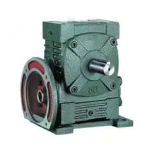
Input: IEC B5 Flange
Motor bolts directly — no input coupling. Motor shaft and first-stage worm shaft co-axial at 0.05 mm TIR. Any IEC B5 frame motor of correct power fits without a motor base or alignment jig.
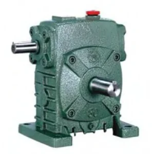
Output: WA-Class Deep Hollow Bore
Driven shaft seats directly into keyed bore — no output coupling. Deep bore engagement (WA-class HL) distributes output torque over large key face area. Shrink disc locking recommended for shock loads.
| Stage Pair | Power (kW) | Ratio | A (mm) | B (mm) | H (mm) | LL/HL (mm) | Flange LZ (mm) | Input Q (mm) | Output LS (mm) | Output S (mm) | Key W×Y |
|---|---|---|---|---|---|---|---|---|---|---|---|
| 40–60 | 0.12 | 200–900 | 258 | 186 | 120 | 100 | 140 | 25 | 50 | Ø22 | 7×4 |
| 50–80 | 0.18 | 200–900 | 314 | 224 | 160 | 130 | 140 | 25 | 65 | Ø32 | 10×4.5 |
| 60–100 | 0.37 | 200–900 | 363 | 247 | 200 | 160 | 160 | 35 | 75 | Ø38 | 10×4.5 |
| 70–120 | 0.37/0.75 | 200–900 | 429 | 295 | 240 | 190 | 160/200 | 35/45 | 85 | Ø45 | 12×4.5 |
| 80–135 | 0.75/1.5 | 200–900 | 505 | 338 | 270 | 215 | 200 | 45 | 95 | Ø55 | 15×5 |
| 100–155 | 1.5 | 200–900 | 565 | 397 | 290 | 235 | 200 | 55 | 110 | Ø60 | 15×5 |
| 120–175 | 2.2/3.0 | 200–900 | 635 | 444 | 335 | 280 | 250 | 65 | 110 | Ø65 | 18×6 |
| 135–200 | 3.0 | 200–900 | 691 | 505 | 375 | 310 | 250 | 65 | 125 | Ø70 | 20×7 |
0.12–3.0 kW
IEC B5 Flange Input
Deep Hollow Bore Output
Double Self-Locking
Zero Couplings Both Ends
The EDA’s Three-Way Integration — Ultra-High Ratio, Zero Couplings, Shaft-Mount
No other single unit in the standard worm gear reducer catalogue achieves all three simultaneously. Understanding why requires seeing what alternatives a design engineer faces without the EDA:
| Specification Need | Without EDA | With EDA |
|---|---|---|
| Ultra-high ratio (200:1+) | Two separate gearboxes in series | One housing |
| No input coupling | Motor base + jaw coupling required | IEC flange — motor bolts direct |
| Shaft-mount output | Solid shaft + output coupling + guard | Hollow bore — shaft slides in direct |
| Self-locking power-off hold | External brake required | Double self-locking — both stages |
| Component count | Motor base + coupling + 2 gearboxes + inter-shaft + output coupling | One EDA unit |
EDA Advantages — Why This Unit Changes the Slow-Speed Shaft-Mount Specification
Only Unit Combining All Three: 200-900:1 + IEC Flange + Hollow Bore
The EDA is the only catalogue unit that simultaneously achieves ultra-high reduction, IEC motor-direct input, and shaft-mount hollow bore output. The EA/FCEA achieves high ratio with either flange input OR solid shaft output but not hollow bore. The WDKA/WDKS achieve IEC flange + hollow bore but only to 60:1 single stage. The EDA crosses both limits.
Double Self-Locking Through the Hollow Bore
Both worm stages self-lock simultaneously on power-off. The self-locking torque is transmitted directly to the driven shaft through the hollow bore key connection — no output coupling slip risk can compromise the locked state. For gate valve stems and loaded hoist drums, the double self-locking delivered through the bore connection provides more secure load-holding than any external brake arrangement.
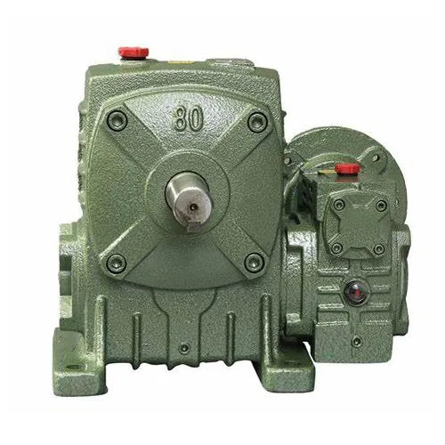
135-200 Stage Pair — 3.0 kW at 900:1
The 135-200 stage pair extends the EDA to the widest power and torque coverage in the D-variant E-series hollow-bore range. At 900:1 with 3.0 kW input, the theoretical output torque exceeds 8,500 Nm before service factor — one of the highest output-torque-to-input-power ratios achievable in a single shaft-mount unit. This covers large gate valve stems, heavy industrial stirrer drives, and large-diameter antenna elevation drives that would require multi-tonne helical gearbox sets in competing specifications.
IEC Flange — Any Standard Motor, No Motor Base
The EDA IEC B5 flange accepts any standard motor from the local electrical stock. In remote Australian gate valve actuator installations where motor replacement must be possible without specialist parts sourcing, the IEC standard flange is a direct availability advantage. Any IEC 63–100 frame motor in the correct power range bolts directly; no custom motor bracket, no alignment jig, no coupling spider inspection.
WA-Class Bore Depth — Shock-Tolerant Connection
The EDA output bore is WA-class — deeper than the standard WK bore, providing more key face engagement length and proportionally lower surface pressure at the same output torque. At the high torques that the EDA produces at 400:1+ (which can exceed 2,000–5,000 Nm at larger stage pairs), the WA bore depth is essential to keep bore fretting within tolerable levels. A shallower bore at these torque levels would fail through key fretting within months.
Single-Unit Maintenance — Both Stages One Service Point
The EDA integrated housing services both worm stages from a single oil fill/drain system. In gate actuator and slow-speed infrastructure applications where the unit is accessed infrequently and each service visit carries travel cost, a single oil change per service interval versus two separate service points on an equivalent multi-unit arrangement is a visible lifecycle cost reduction.
Applications — EDA in Ultra-Low Speed Shaft-Mount Australian Drives
- 🌊 Gate Valve and Penstock Actuators — Zero-Coupling Double Self-Locking (self-locking worm gearbox)
EDA 80-135 to 120-175 at 400:1–800:1, bore-mounted directly on the valve stem shaft. No output coupling between reducer and stem — the stem slides into the hollow bore. IEC motor bolts to the input flange. Double self-locking holds the valve at any travel position on power-off without hydraulic pressure or electrical brake. At 600:1 with 0.75 kW input, output torque ≈ 1,350 Nm — sufficient to operate 300–500 mm diameter sluice gates in Australian water infrastructure. - 🧪 Biogas Stirrer Drives — Shaft-Mount on Impeller Shaft
EDA 60-100 to 80-135 at 300:1–500:1 for slow-speed biogas and anaerobic digestion impeller drives. The hollow bore mounts directly on the impeller shaft (typically Ø38–55 mm); the IEC motor bolts directly to the reducer input flange. No motor base, no coupling guard, no output coupling — in an enclosed gas-tight digester head penetration, removing every coupling and rotating exposed component reduces the number of potential gas-leak points and simplifies the shaft-seal design. - 🌾 Precision Agricultural Implement Drives
EDA 40-60 to 60-100 at 200:1–400:1 for high-precision seed singulation, micro-dose fertiliser metering, and slow-speed conveyor positioning drives in Australian controlled-environment agriculture and precision seeding equipment. The hollow bore shaft-mounts directly on the implement’s metering roller shaft; the compact IEC flange motor attaches directly without a motor base protruding into the implement’s structure. For PTO-input variants on field implements, a yoke adaptor replaces the IEC motor at the EDA input flange — see agricultural PTO shaft resources for adaptor sizing. - 📡 Antenna and Telescope Elevation Drives — High-Torque Shaft Mount
EDA 100-155 to 135-200 at 600:1–900:1 for remote Australian radio telescope and satellite dish elevation drives. The hollow bore mounts on the elevation axis shaft (Ø60–70 mm); the IEC motor bolts directly with no alignment jig. Self-locking holds the dish at the programmed elevation angle through wind events and power interruptions without any mechanical lock or electrical brake. At 135-200 stage pair with 3.0 kW input at 900:1, output torque exceeds 8,000 Nm — covering very large dish elevation axes without a separate gearbox cascade. - 🔄 Industrial Slow-Speed Conveyor and Turntable Positioning
EDA 70-120 to 100-155 at 300:1–600:1 for OEM slow-speed conveyor positioning drives, rotary indexing tables, and turntable drives where the output shaft is large-diameter and the drive must shaft-mount without a separate coupling. The EDA replaces what would otherwise be a worm reducer + a secondary helical reduction stage + an output coupling as a single zero-coupling shaft-mount unit. For further guidance on gearbox selection for Australian industrial conveyor applications, refer to resources at gearboxagricultural.com.
Drive Accessories and Component Selection for EDA
IEC Motor — Small Frame, High Torque Multiplied
At EDA 40-60, the input flange accepts IEC 63–71 frame motors (0.12–0.18 kW). These small motors produce very large output torques when multiplied by 200–900 reduction. Before specifying, confirm the motor shaft length against T×V bore depth — small IEC frame motor shaft lengths vary significantly between manufacturers and a bottomed-out shaft prevents correct flange seating on the compact first-stage housing.
Shrink Disc — Mandatory at Large Stage Pairs
For EDA 80-135 and above, output torques at high ratios can exceed 1,000–5,000+ Nm. A set screw cannot reliably transfer these torques without progressive loosening. Shrink disc locking is mandatory for stage pairs 80-135 and above — specify by bore diameter S and the calculated torque with service factor. For stage pairs 40-60 to 70-120 at smooth loads, a set screw is acceptable; for any shock load at any stage pair, always use a shrink disc.
PAO Synthetic Oil — Both Stages
Two fill/drain points — one per stage. For EDA units in continuous duty in Australian summer ambient above 35°C, PAO synthetic ISO VG 220 in both stages extends the thermal ceiling and the service interval simultaneously. Mineral oil at 40°C ambient with high-ratio continuous duty commonly constrains the EDA before mechanical torque limits are reached — PAO removes this constraint in most practical applications.
Torque Arm — Large Housing Weights
EDA 120-175 and 135-200 are large units (estimated 90–150+ kg with motor). In shaft-mount configuration, the torque arm must carry both the reaction torque (which is enormous at high ratios) and the gravitational weight moment of the assembly. Use a heavy-duty dual-rubber-bush arm; specify for the combined load, not just reaction torque. This is the most commonly under-specified component on large EDA shaft-mount installations.
Temperature Monitoring — Large Stage Pairs
For EDA 100-155 and 135-200 in continuous duty, a PT100 sensor at the housing gives advance warning of thermal overload before worm wheel failure — which in a unit of this size is a costly and difficult repair. SCADA-connected monitoring on large gate actuator installations pays for itself in avoided emergency service calls, particularly in remote Australian water infrastructure where repair travel is a significant cost.
Oil Orientation — Both Stages Independently
Non-standard installation orientations change the effective oil level in both stages independently. Both stages must have correct oil levels for the installed orientation — failure in either stage results in partial oil starvation with rapid bronze wheel wear. Submit your orientation drawing to the technical team before commissioning on any non-horizontal installation.
Maintenance Schedule — EDA Series
| Interval | Task | EDA Note |
|---|---|---|
| First 500 hr | Flush both stages; shrink disc re-torque; flange bolt check | Inspect bore face for fretting — the large output torques from high ratios concentrate on the bore key even at WA depth; any rust-brown powder at the bore face requires immediate shrink disc re-torque to full specification |
| 2,500 hr | Full oil change both stages; all seals; shrink disc bolts cross re-torque | At large stage pairs (100-155, 135-200), inspect flange face gasket — the large motor weight concentrated at the flange face can accelerate gasket creep and oil weep at this interface |
| 5,000 hr | Remove bore from shaft; bore zone inspection; inter-stage bearing play | Measure bore internal diameter — high output torques at large stage pairs can progressively widen the bore beyond H7 tolerance; replace housing if bore widening exceeds 0.05 mm |
For EDA stage pair and ratio selection matched to your application’s output speed, torque, and shaft diameter requirements, thermal rating assessment at your specific duty cycle and Australian ambient temperature, and shrink disc specification for large stage pairs, contact the engineering team at our worm gearbox technical portal. Enquiries about gate actuator and infrastructure applications are welcome via the technical enquiry page.