Description
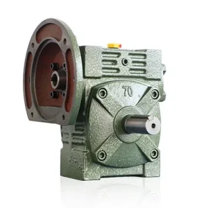
Technical Specifications — FA Series Double Worm Gear Reducer
Output Speed Reference — Standard 4-Pole Motor at 1,450 rpm Input (50 Hz)
1/90 → 16.1 rpm
1/100 → 14.5 rpm
1/120 → 12.1 rpm
1/150 → 9.67 rpm
1/180 → 8.06 rpm
FA fills the gap: single-stage maximum is 60:1 (24.2 rpm) · E-series minimum is 200:1 (7.25 rpm) · FA covers everything between
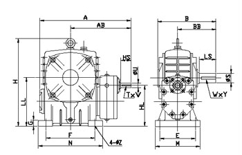
| Size | Ratio | A (mm) | AB (mm) | B (mm) | BB (mm) | E (mm) | F (mm) | H (mm) | HL (mm) | LL (mm) | Input HS (mm) | Input U (mm) | Output LS (mm) | Bore S (mm) | Key W×Y |
|---|---|---|---|---|---|---|---|---|---|---|---|---|---|---|---|
| 80 | 80–180:1 | 317 | 213 | 210 | 140 | 135 | 180 | 273 | 130 | 160 | 35 | 15 | 65 | Ø32 | 10×4.5 |
| 100 | 80–180:1 | 390 | 258 | 230 | 155 | 155 | 220 | 340 | 160 | 200 | 40 | 18 | 75 | Ø38 | 10×4.5 |
| 120 | 80–180:1 | 437 | 282 | 285 | 185 | 180 | 260 | 405 | 190 | 240 | 40 | 20 | 85 | Ø45 | 12×4.5 |
| 135 | 80–180:1 | 496 | 321 | 320 | 210 | 200 | 290 | 455 | 210 | 270 | 50 | 25 | 95 | Ø55 | 15×5 |
| 155 | 80–180:1 | 559 | 367 | 387 | 252 | 220 | 320 | 486 | 280 | 390 | 60 | 30 | 110 | Ø60 | 15×5 |
| 175 | 80–180:1 | 630 | 407 | 407 | 262 | 250 | 350 | 556 | 260 | 335 | 75 | 35 | 110 | Ø65 | 18×6 |
Sizes
80 · 100 · 120 · 135 · 155 · 175
Ratio Range
80 · 90 · 100 · 120 · 150 · 180
Output Bore Range
Ø32 – Ø65 mm
Input
Through-shaft — either face
Self-Locking All 6 Ratios
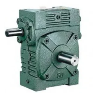
Through-Shaft Input — Flex Motor Position
Hollow Bore — No Output Coupling
Fills 60:1–200:1 Catalogue Gap
Why the 80–180:1 Range Exists and Why Single-Stage Can’t Cover It
Three approaches attempt to reach 80:1–180:1 output reduction. Each has a practical problem that the FA’s dual-stage architecture resolves:
❌ Option A — Single-Stage at 80:1+
Above 60:1, the worm lead angle falls below approximately 5°. Manufacturing precision degrades, efficiency drops to 30–40%, and sustained heat output under any meaningful continuous load exceeds housing thermal rating. A 100:1 single-stage worm is not available as a catalogue product for legitimate engineering reasons — the geometry is impractical in continuous service.
⚠️ Option B — VFD Reduction Below 25 Hz
Running a 60:1 single-stage unit with a VFD at 12–18 Hz achieves the speed target — but a standard TEFC motor loses cooling fan airflow below 25 Hz and overheats in sustained service. A thermally-rated force-cooled motor adds cost and procurement complexity. The VFD control also requires tuning for very low-frequency stability. Acceptable as a workaround; not the clean engineering solution the FA provides.
✅ Option C — FA Series Double-Stage
Two stages, each in the 8:1–14:1 per-stage range where worm efficiency peaks at 70–80%. Stage ratios multiply to yield the 80:1–180:1 overall range. Motor runs at rated speed with rated cooling. Both stages self-lock. Hollow bore output direct-mounts to the driven shaft. FA overall efficiency at 100:1 is approximately 55–65% — measurably better than an E-series unit operated at its minimum 200:1 ratio.
Six Practical Advantages of the FA Configuration
Six Ratios Across a Gap No Other Unit Spans
80:1, 90:1, 100:1, 120:1, 150:1, 180:1 — precisely the output speeds that fall below the single-stage ceiling and above the E-series floor. For Australian drives requiring 8–18 rpm from a standard 4-pole motor, these six ratios cover the full range without compromising motor efficiency or stretching the reducer beyond its thermal capability.
Through-Shaft Input — Motor Position Unconstrained
The through-shaft input provides motor coupling access from either first-stage housing face. In retrofit situations where the existing machine structure determines motor position rather than the gearbox designer, the FA accommodates the motor on whichever side the structure allows — without changing the unit specification or adding adaptor hardware.
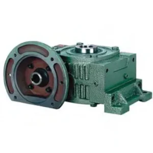
Hollow Bore — Output Coupling Eliminated
The driven shaft seats directly into the keyed bore and locks with a locking element or shrink disc. No output coupling body, no coupling guard, no alignment step at the output. In slow conveyor head shaft drives, gate actuator stem drives, and slow-speed mixer shaft drives, this removes both the coupling maintenance item and the rotating coupling body from the machine envelope simultaneously.
Self-Locking at All Six Ratios — No Brake Required
Both FA worm stages operate in the self-locking lead angle range at every available ratio from 80:1 through 180:1. The hollow bore holds the driven shaft stationary on power-off without an external brake, motor spring-set disc brake, or electrical hold current. For gravity-loaded conveyors, inclined positioning drives, and gate actuators where a static hold is required between operating cycles, the FA eliminates the brake from the specification at every ratio.
Better Thermal Performance Than E-Series at These Ratios
E-series stages at 200:1 minimum ratio run each stage at individual ratios of approximately 14:1+ — near the low end of worm efficiency. The FA at 100:1 distributes the ratio across two stages at approximately 10:1 each, where each stage operates near peak worm efficiency. Overall FA efficiency at 100:1 (approximately 55–65%) is materially better than E-series efficiency at 200:1 (approximately 45–55%), reducing heat generation and thermal management requirements under Australian summer conditions.
Size 175 at Ø65 mm Bore — Heavy-Duty Large-Shaft Drives
FA175 provides Ø65 mm hollow bore with HL = 335 mm bore engagement depth. At this size, the bore distributes output torque from 80:1–180:1 reduction across 335 mm of key face contact — adequate for the high output torques generated at these ratios on large shafts. For bulk handling conveyor head shafts and heavy industrial positioning drives in Australian mining requiring 8–18 rpm at Ø55–65 mm shaft diameters, FA175 covers the specification directly.
Applications — FA Series in Australian Slow-Speed Shaft-Mount Drives
- ⛓️ Slow Conveyor Head Shaft Drives — 10–16 rpm (shaft mounted worm gearbox)
FA size 100–155 at 100:1–150:1 for slow bulk material conveyor head shaft drives where the belt velocity requires output speeds of 10–16 rpm at a head shaft diameter of Ø38–60 mm. The FA hollow bore mounts directly on the head shaft without an output coupling; the through-shaft input couples to the motor on whichever side the conveyor structural bay allows. Self-locking prevents belt reverse-travel under gravity load on inclined sections when power is removed. - 🌊 Gate Valve Actuators — Precise Low-Speed Travel
FA size 100–135 at 120:1–180:1 for gate valve and sluice gate actuators requiring 8–12 rpm travel speed — below what a single-stage reducer produces at standard VFD frequencies without motor de-rating. The hollow bore seats directly on the valve stem. Self-locking holds the gate at any travel position on power-off without hydraulic pressure or a separate electrical latch. Through-shaft input couples to the motor on whichever side the valve head frame permits. - 🧫 Slow Mixer and Agitator Drives — Correct Speed Without VFD Penalty
FA size 80–120 at 80:1–100:1 for slow-speed paddle mixers, ribbon blenders, and agitators where the impeller must rotate at 14–18 rpm for correct mixing without product shear damage. The FA produces these speeds directly from a standard 4-pole motor running at full rated frequency — motor thermal rating is fully utilised, unlike a VFD-throttled arrangement where the motor runs cool but at reduced airflow. The hollow bore mounts directly on the impeller shaft. - 🌾 Agricultural Metering and PTO Implement Drives
FA size 80–120 at 80:1–120:1 for slow-speed metering and discharge drives on Australian grain handling, feed milling, and compost turning equipment. The hollow bore shaft-mounts directly on the metering shaft; the through-shaft input accepts PTO connection from either side of the implement depending on tractor configuration. For PTO adaptor sizing and slip clutch specification, see agricultural PTO shaft resources. For broader gearbox selection guidance in Australian agricultural equipment applications, visit gearboxagricultural.com. - 🏭 OEM Incremental Indexing and Positioning Drives
FA size 100–135 at 150:1–180:1 for OEM slow-speed machine positioning drives where each motor rotation must produce a small, repeatable angular increment of the output shaft. At 180:1, a 0.1-second motor pulse at 1,450 rpm moves the output shaft approximately 0.8°. The FA’s double-stage worm geometry inherits lower backlash than a hypothetical single 180:1 stage and self-locks between pulses — useful for incremental indexing tables, rotary positioning fixtures, and precision feed mechanisms in Australian precision manufacturing.
Drive Accessories, PTO Integration and Component Selection
Input Jaw Coupling — Either Stub
Standard elastomeric jaw coupling from either FA through-shaft stub. For shock or cyclic loads, a curved-jaw coupling with polyurethane spider absorbs startup torque peaks before they reach the first-stage worm mesh. Seal the unused input stub with the blanking cap and replace the lip seal at every 2,500-hour oil service — failed blanking seals are the primary contamination ingress path in dusty Australian agricultural environments.
PTO Shaft Adaptor + Friction Slip Clutch
Yoke-end PTO adaptor couples to either FA input stub. A friction slip clutch at 1.5× rated input torque is mandatory for agricultural implement applications — tractor PTO engagement surges and field jams generate transient torques of 5–8× rated that the first-stage worm mesh must be shielded from. The through-shaft input accommodates PTO from either implement side without changing the FA unit specification.
Bore Locking — Set Screw or Shrink Disc
For smooth continuous loads on FA size 80–100, a set screw is acceptable. For cyclic, reversing, or sustained high torque on sizes 120–175, a shrink disc is the correct specification — progressive set screw loosening under cyclic torque is the most common output bore failure mode in these applications and is fully preventable by shrink disc specification at the initial installation stage.
Oil — Two Independent Fill Points
The FA has two drain/fill points — one per worm stage — both requiring independent service at each oil change interval. ISO VG 220 mineral oil for standard duty below 35°C ambient. For continuous duty at ratios ≥ 120:1 and Australian summer ambient above 35°C, PAO synthetic ISO VG 220 in both stages is recommended — extending the thermal ceiling by 10–15% and the service interval to 5,000 hours.
Torque Arm (Shaft-Mount Configuration)
In shaft-mount configuration the torque arm must resist the hollow bore reaction torque and the gravitational moment of the motor-plus-FA assembly. At size 155–175 with motor, total weight can exceed 80–120 kg. Calculate the gravitational moment at the arm anchor using the actual motor centre-of-gravity offset — it is particularly significant when the output shaft is horizontal and the motor is positioned above or below the shaft centreline.
Thermal Monitoring — Large Sizes at Hot Ambient
Two-stage worm efficiency at 30–40% heat rejection per kW of input means thermal verification is essential for FA155 and FA175 in continuous duty above 40°C Australian ambient. Always confirm the thermal rating at your actual input power, ratio, duty cycle, and site ambient before finalising the specification. For remote installations with infrequent visual inspection, a PT100 sensor on the second-stage housing provides advance warning of thermal overload before worm wheel failure.
Maintenance Schedule — FA Series Double-Stage (Australian Conditions)
| Interval | Task | FA Double-Stage Note |
|---|---|---|
| First 500 hr | Flush both stages; re-torque bore locking element; inspect blanking cap seal | Flush removes bronze break-in particles from both stages before they circulate into bearings. Higher FA efficiency vs E-series means less break-in heat — but particles still form and must be removed at first service regardless. |
| 2,500 hr | Full oil change both stages; replace all seals; re-torque shrink disc; replace blanking cap lip seal | Replace blanking cap lip seal proactively in dusty Australian field environments — the through-shaft input creates a seal on both sides of the first-stage housing; the inactive stub seal is the one most often overlooked and the primary contamination ingress path. |
| 5,000 hr | Remove bore from shaft; inspect bore zone and shaft; check inter-stage shaft bearings | Inspect the inter-stage connecting shaft independently — this shaft carries both radial and axial loads at intermediate speed and its bearings age differently from the input and output bearings. Measure bore diameter against nominal H7 tolerance; bore widening beyond 0.05 mm indicates shrink disc under-clamping that must be addressed before re-installation. |
| On overload event | Inspect both worm wheel bronze faces; check bore keyway for fretting | After a jam or overload event, inspect both worm wheel bronze faces before returning to service — a single severe overload can cause subsurface fatigue initiation that leads to pitting failure within the next 500 hours of normal operation if not identified. |
For FA size selection against your required output speed, thermal rating verification at your Australian site ambient and duty cycle, bore locking element specification, oil orientation confirmation for non-standard installation angles, and project procurement scheduling, contact the engineering team at our worm gearbox technical portal. For time-sensitive procurement, reach us directly via the technical enquiry page with your required size, ratio, bore diameter, and duty conditions.
What Australian Engineers Say About the FA Series
“We replaced two single-stage 60:1 units running at reduced VFD frequency on our slow conveyor line with FA-135 at 120:1. The motors went back to running at full speed and full cooling — we haven’t had an overtemperature trip since. The hollow bore saved us a complete coupling overhaul on both head shafts.”
David C.
Maintenance Engineer · Bulk Handling, Western Australia
“Gate actuator for a 400 mm irrigation sluice gate — needed 10 rpm travel with guaranteed lock on power failure. The FA-120 at 150:1 fit directly on the existing stem, motor coupled from the left side where our steel frame had clearance. Six months in the field, no issues. Self-locking holds the gate in any position through power outages.”
Michael T.
Project Engineer · Irrigation Infrastructure, South Australia
“Specified FA-100 at 100:1 for a ribbon blender drive on our compost turning line — 14.5 rpm output from a direct-online motor. The product quality improved noticeably versus the previous VFD-throttled arrangement, which we suspect was running the paddles too slow at the temperature limits. Strong unit, straightforward to maintain.”
Sophie R.
Production Manager · Organics Processing, Queensland
“Used FA-80 at 90:1 on a precision seeder metering shaft — 16 rpm from a compact 0.37 kW motor. Fits inside the implement frame where a larger unit wouldn’t. The PTO adaptor on the through-shaft input was clean to install. Two seasons in Queensland paddock conditions with PAO oil — no issues, no leaks.”
Andrew F.
OEM Design Engineer · Precision Seeding Equipment, Victoria