Description
Technical Specifications
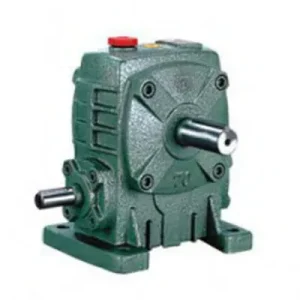
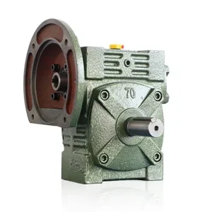
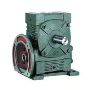
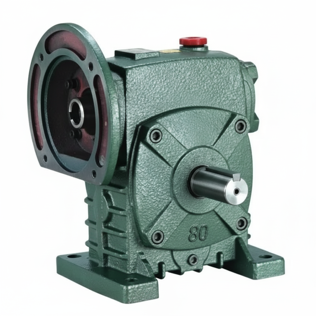
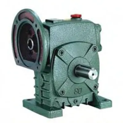
The WPDS series worm gear reducer is built on the WD hollow-bore platform with a key structural addition: the worm shaft is extended and supported on both the input and non-input sides, leaving both shaft ends accessible outside the housing. This dual-access geometry allows auxiliary attachments — electromagnetic brakes, back-stop ratchet mechanisms, position encoders, or secondary input drives — to be fitted to the tail end of the worm shaft without custom housing modifications. Twelve frame sizes from 40 to 250 cover the full industrial speed-reduction range.
| Parameter | Range / Value | Notes |
|---|---|---|
| Frame Sizes | 40 – 250 | 12 standard sizes |
| Gear Ratio | 10:1 – 60:1 | Single stage |
| Input Type | Hollow bore (motor shaft) | WD architecture |
| Tail Shaft Access | Both worm shaft ends exposed | Dual-access feature |
| Output Torque | 19 – 2,745 N·m | Size-dependent |
| Input Power | 0.12 – 33.2 kW | Motor-dependent |
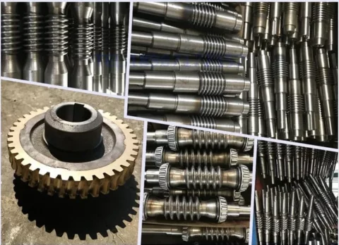
| Worm Material | 45# Steel, induction-hardened | 56–62 HRC surface |
| Worm Wheel | Tin Bronze ZCuSn10Pb1 | Conjugate hobbed profile |
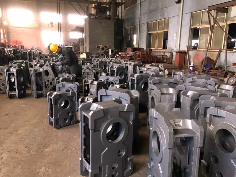
| Housing | Cast Iron HT200 | Ribbed convective cooling |
| NEMA Compatibility | 56C – 250TC | Size-dependent frame |
| Lubrication | Oil bath, ISO VG 220/320 | Grease option available |
| Certifications | ISO 9001 / CE / SGS | Quality assured |
Why Dual Shaft Access Solves Real Machine Design Problems

In the standard WPS configuration, the motor shaft enters from one side of the worm shaft bore and the opposite shaft end is enclosed within the housing end cap. This is entirely adequate for a simple motor-to-load connection. However, many industrial machines require more than a straight input-to-output power path: a conveyor jam-protection back-stop, a holding brake for a gravity-loaded lift, a hand-wheel override for emergency operation, or a rotary encoder for closed-loop speed control — all of these accessories require mechanical access to the worm shaft beyond the motor end.
The WPDS resolves this by engineering a second bearing seat into the non-motor-side end cap, extending the worm shaft through this bearing and out of the housing with a keyed shaft stub. This stub accepts any standard accessory with a bore-and-keyway fitting — from electromagnetic disc brakes through to back-stop ratchet mechanisms and incremental encoders — without requiring a custom housing modification or secondary mounting bracket welded to the machine frame.
Brake Integration
Electromagnetic disc brakes bolt directly to the tail shaft stub, providing dynamic and static holding torque for vertical lift and gate-control applications without additional mounting hardware.
Encoder Mounting
Incremental or absolute rotary encoders mount on the tail shaft for closed-loop motor speed feedback, avoiding the need for an external encoder coupling and shaft on the motor.
Back-Stop Ratchet
One-way sprag clutch or ratchet units prevent reverse rotation under gravity load in inclined conveyor applications where self-locking alone is insufficient for safety certification.
Manual Override
A hand-wheel or torque wrench adapter on the tail shaft enables manual positioning during power outages or commissioning without removing the motor or coupling.
WPDS Structural Architecture and Load Path Analysis

The dual-access shaft configuration in the WPDS requires a more complex bearing arrangement than the standard WPS. Where the WPS uses bearings only at the motor-side and mid-housing positions to support the worm shaft, the WPDS adds a third bearing set in the tail-end cap. This third bearing position absorbs the axial reaction forces from accessories mounted on the tail stub while preventing bending moment transfer into the worm thread contact zone — a critical requirement for maintaining tooth load distribution accuracy at rated torque.
Bearing Arrangement and Load Path
The three-bearing worm shaft support creates a statically determinate system: the motor-side bearing handles the combined radial load from the motor shaft weight and the worm-wheel tooth normal force component; the mid-housing bearing provides primary radial support at the worm thread mesh; the tail-end bearing absorbs the axial load from any accessory mounted on the tail stub, preventing this load from travelling along the worm shaft and disturbing the axial preload on the mesh-zone bearing pair. This load isolation is what makes the WPDS mechanically sound for brake and encoder applications that generate significant axial forces through their shaft connections.
Thermal Behaviour at Extended Duty
The additional bearing at the tail end represents a small additional friction source in the gear train. In practice, this contributes less than 0.5% additional heat generation at rated load compared to a WPS of equivalent size — well within measurement uncertainty for field thermal surveys. For continuous duty applications above 75% load fraction, the same thermal management guidelines apply to WPDS as to WPS: use ISO VG 320 synthetic oil above 30 °C ambient, or specify the optional external cooling fan for enclosed environments.
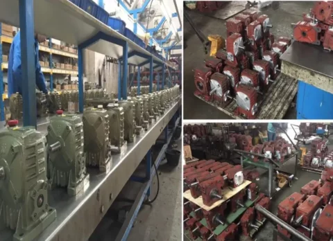
Core Components, Related Sub-Assemblies & Mating Drive Elements
The WPDS is assembled from the same base components as the WPS, with structural additions at the tail-end to support the dual-access feature. Understanding the full component list is essential for field maintenance teams managing replacement part inventories.
Hollow Bore Dual-Extension Worm Shaft
The worm shaft is bored through to accept the motor shaft from the input end, with the thread machined centrally and the opposite shaft end extending 30–80 mm beyond the tail bearing (size-dependent). The tail stub carries the same keyway standard as the motor end, allowing any keyed-hub accessory to be fitted. Thread geometry follows the ZA Archimedean profile for standard tool re-grinding compatibility.
Three-Point Worm Shaft Bearing Support
Two deep-groove ball bearings at the motor-side and mid-housing positions handle the primary radial and axial mesh loads. A third angular-contact bearing at the tail-end cap isolates accessory-generated axial forces from the mesh zone. All three bearing positions include labyrinth seals between the bearing and the external environment to prevent lubricant migration from the housing oil bath into mounted accessories.
Tin Bronze Worm Wheel — Replaceable Rim Design
For sizes 40–100, the wheel is a solid ZCuSn10Pb1 bronze casting. Sizes 120–250 use a replaceable bronze rim pressed and keyed onto a cast iron hub, allowing the rim to be replaced independently without removing the hub from the output shaft — reducing field overhaul time from 4 hours to under 90 minutes for large frame sizes.
Dual Tail-End Sealing System
The tail stub exit point uses a double-lip rotary oil seal backed by a labyrinth groove to prevent gear oil migration toward mounted accessories. This is critical for electromagnetic brakes, which lose holding torque rapidly when contaminated with oil. The seal is designed for replacement without dismantling the housing — accessible from the outside after removing the tail-end cap bolts.
Compatible Accessory Fitments
The tail stub is dimensioned to accept: DC electromagnetic brakes (24V or 230V coil), spring-applied failsafe brakes, manual back-stop ratchet assemblies, centrifugal speed governors for over-speed protection, and standard hollow-shaft incremental encoders. Custom stub diameters for non-standard accessories are available with a 2–3 week lead time. Drive shaft integration options, including flexible couplings for CV shaft drive configurations, are also supported at the tail-stub end for multi-directional output arrangements.
HT200 Housing with Extended End Cap
The cast iron housing of the WPDS is dimensionally longer along the worm axis than the equivalent WPS to accommodate the tail bearing seat and stub extension. External footprint increases are limited to the worm axis direction — mounting bolt pattern and output shaft dimensions remain identical to the WPS equivalent, allowing WPDS to be substituted into an existing WPS machine design when the dual-access feature is subsequently required.
Industry Applications Where the WPDS Dual-Access Design Delivers Advantage
The WPDS suits any application where a standard worm reducer is required but a secondary function — braking, sensing, or manual control — needs physical access to the worm shaft. Across Australian industry, the most frequent deployment scenarios are:
Inclined Conveyor & Elevator Drives
Inclined belt conveyors carry a reverse-running risk under gravity during motor coast-down. The WPDS tail stub accepts a back-stop ratchet or electromagnetic brake that prevents rollback without requiring a separate shaft or housing modification.
Stage & Architectural Moving Equipment
Flying systems, motorised scenery, and architectural feature drives require both a failsafe brake (on the tail) and a manual emergency descent capability — both achievable simultaneously with the WPDS dual-access shaft.
Automated Gate & Barrier Systems
Security gates and boom barriers must hold position without power and allow manual release. The WPDS tail stub handles both the holding brake and the manual release lever without additional machining or external coupling shafts.
Variable-Speed Closed-Loop Process Lines
Packaging machines and printing lines running under VFD control benefit from a worm-shaft-mounted encoder for speed feedback, avoiding the encoder coupling between motor and gearbox that introduces phase lag in position control loops.
Winch & Tensioning Equipment
Marine and industrial winches require the drive to hold load under power failure. The WPDS integrates a spring-applied failsafe brake on the tail stub, engaged automatically on power loss without external wiring to a separate brake housing.
Selecting the Correct WPDS Frame and Accessory Combination
Frame selection for the WPDS follows the same torque-ratio-thermal calculation sequence as the WPS. The additional consideration specific to the WPDS is the tail-stub load: the accessory mounted on the tail end imposes a radial overhang load and possibly an axial load on the tail bearing. The tail bearing is sized to accept the standard accessory load for each frame size, but for large brakes or high-speed encoders generating significant radial loads, the accessory manufacturer’s shaft load specification must be checked against the WPDS tail bearing capacity listed in the catalogue.
The brake holding torque must exceed the maximum output shaft reverse torque (full load × gravitational component for inclined conveyors, plus a 1.5× safety factor per AS 1755 material handling standards).
Choose a hollow-shaft encoder with bore diameter matching the tail stub size and a maximum permissible shaft load above the encoder’s own inertia-driven load at the maximum motor acceleration rate.
Check the WPDS frame-specific tail stub length against the accessory bore depth — the motor shaft must be fully engaged in the hollow bore at the same time as the accessory is fully seated on the tail stub.
For technical selection support, dimensional drawings, and accessories compatibility matrices, visit the product catalogue homepage, or contact the engineering team for application-specific guidance.
Maintenance Programme for the WPDS Compact Worm Gearbox
The WPDS compact worm gearbox maintenance schedule mirrors the WPS, with one additional inspection task: the tail-end seal condition and oil migration check at the accessory interface. For brake-equipped WPDS units, the brake air gap should be verified at 2,500-hour intervals, as incremental wear of the brake disc reduces air gap until the brake drags at operating temperature — a progressive efficiency and thermal issue that can be prevented entirely with scheduled gap inspection.
Monthly
Visual seal check at tail stub exit; oil level via sight glass; breather plug clear
300–500 h
First oil change; inspect tail bearing for contamination from accessory side
2,500 h
Routine oil change; check brake air gap (if fitted); replace tail stub seal if worn
10,000 h
Full bearing inspection; replace bronze wheel if pitch wear exceeds 5% of module
For spare parts, technical documentation, or to discuss a maintenance contract for multiple WPDS units across a site, contact the engineering and service team directly.